


Manual
EIM 316/336 interface application for setup and configuration of MMIMyK
3
© Danfoss A/S (AC-MCI/sw), 2014-03
DKRCC.PS.RQ0.C2.02 / 520H8422
2. References
MyK Manager
(A password and login are needed in order to download the application)
MMIMyK Instruction
http://dila.danfoss.net/literature/dkrc/AC-E-IT_MMIMYK_DKRCC.PI.RJ0.
MMIMyK software
download guide
http://dila.danfoss.net/literature/dkrc/AC-E-IT_MMIMYKSwDownload-
Guide_DKRCC.PS.RJ0.B1.02_520H5547_Low.pdf
MMIMyK Manual
http://dila.danfoss.net/literature/dkrc/ITDE_GD_MMIMYK_RS8FP202_EN.
3. Loading the
application into
the MyK
There are two ways to load the application into
the MyK. The first is to use the MyKManager
program which lets you easily connect to the
MyK (please refer to the MMIMyK software
download guide). The other is to manually copy
the files onto a SD/MMC card and inserting this
card into the MyK.
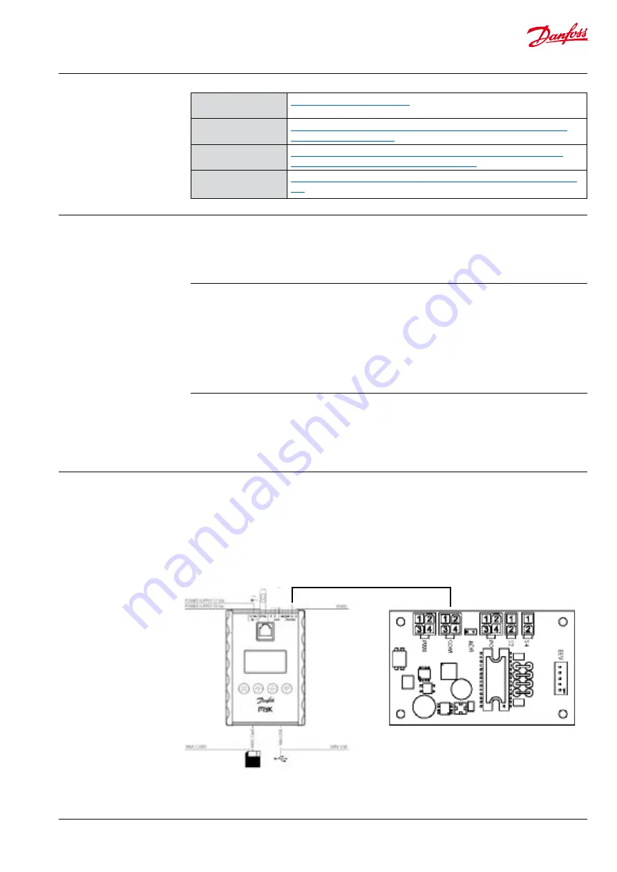
4. Connecting
the MyK
The MyK needs to be connected to a power
supply. Three options are available for this, it can
run either on a 12 V DC supply, a 24 V AC supply, or
it can be powered through the USB connection.
The MyK is connected to the EIM through the
modbus port (RS485), which is wired to the KM5
connector on the EIM.
D+ is connected to KM5,2
D- is connected to KM5,3
GND is connected to KM5,1
3.2 Copying
The downloaded program files (app.pk and
mmimyk.cfg) can be copied to a SD or MMC card
using the Windows explorer or a similar file
manager.
First create a folder on the SD/MMC card, the
name of the folder must be 8 characters or less.
Then copy the two files into the folder. The SD/
MMC card can now be inserted into the MyK.
3.1 MyKManager
Start the MyKManager program on the PC, and
connect the MyK to the PC using the USB cable.
The screen displays the available drives in the
MyK, where drive 0:/ is the MyK’s own internal
memory, and drive 1:/ is the external memory
(SD/MMC card). If no SD/MMC card is mounted,
only drive 0:/ is displayed.
Create a folder on either the internal or external
drive, by right-clicking on the drive’s name and
selecting “New folder”. The name of the folder
must be 8 characters or less. Then import the two
files by right-clicking on the folder and selecting
“import files”. Browse to the two files (app.pk and
mmimyk.cfg), select them and click “import”. The
MyKManager program can now be closed.
Modbus connection
ESC Up Down Enter
EIM 316 / 336


