background image

Installation

System cleanliness

The refrigerant compression system, regardless 
of the type of compressor used, will only provide 
high efficiency and good reliability, along with a 
long operating life, if the system contains solely 
the refrigerant and oil it was designed for. Any 
other substances within the system will not 
improve performance and, in most cases, will be 
highly detrimental to system operations.

The presence of non-condensable substances 
and system contaminants such as metal 
shavings, solder and flux, have a negative 
impact on compressor service life. Many of these 
contaminants are small enough to pass through 
a mesh screen and can cause considerable 
damage within a bearing assembly. The use of 
highly hygroscopic polyol ester oil in R410A 
compressors requires that the oil be exposed 
to the atmosphere as little as possible. System 

contamination is one of main factors affecting 
equipment reliability and compressor service 
life. It is important therefore to take system 
cleanliness into account when assembling a 
refrigeration system.

During the manufacturing process, circuit 
contamination may be caused by:
• Brazing and welding oxides,
• Filings and particles from the removal of burrs
in pipe-work,
• Brazing flux,
• Moisture and air.

Consequently, when building equipment 
and assemblies, the precautions listed in the 
following paragraphs must be taken.

Tubing

Only use clean and dehydrated refrigeration 
grade copper tubing. Tube-cutting must be 
carried out so as not to deform the tubing 
roundness and to ensure that no foreign debris 
remains within the tubing. Only refrigerant grade 
fittings should be used and these must be of 

both a design and size to allow for a minimum 
pressure drop through the completed assembly. 
Follow the brazing instructions on next pages. 
Never drill holes into parts of the pipe-work 
where fi lings and particles can not be removed.

Brazing and soldering

When brazing copper-to-copper connections, 
the use of copper/phosphorus brazing alloy 
containing 5% silver or more with a melting 

temperature of below 800°C is recommended. No 
flux is required during brazing.

Copper to copper  
connections

Do not bend the compressor discharge or suction 
lines or force system piping into the compressor 
connections, because this will increase 
stresses that are a potential cause of failure. 
Recommended brazing procedures and material, 

are described section “Compressor connection”. 
These operations must be performed by a 
qualified personnel in compliance with all 
pertinent practices and safety procedures.

Dissimilar metals  
connection

When manipulating dissimilar metals such as 
copper and brass or steel, the use of silver solder 
(5% or more) and anti-oxidant flux is necessary. 

Please contact Danrfoss Technical support for any 
deviation from this guidelines.

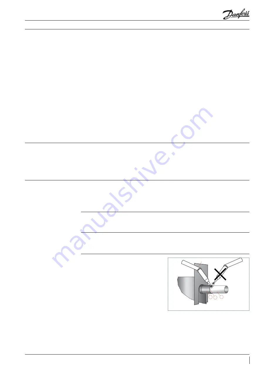
Compressor connection

When brazing the compressor fittings, do not 
overheat the compressor shell, which could 
severely damage certain internal components 
due to excessive heating. Use of a heat shield 
and/or a heat-absorbent compound is highly 
recommended. Due to the relatively sizable 
tubing and fitting diameters a double-tipped 
torch using acetylene is recommended for 
brazing operation on CH scroll compressors. 

heat shield

C B

A

35

FRCC.PC.026.A4.02

Application Guidelines

Summary of Contents for CH290

Page 1: ...Danfoss scroll compressors CH290 CH485 50 Hz R410A Application guidelines http cc danfoss com ...

Page 2: ......

Page 3: ...n 20 High and low pressure protection 20 Cycle rate limit 21 System design recommendations 22 General 22 Essential piping design recommendations 22 Refrigerant charge limit 23 Off cycle migration 24 Liquid flood back 26 Specific application recommendations 27 Low ambient application 27 Low load operation 28 Brazed plate heat exchangers 28 Electronic expansion valve 28 Reversible heat pump systems ...

Page 4: ... the orbiting scroll in grey traces a circular path around the centre of the fixed scroll in black This movement creates symmetrical compression pockets between the two scroll elements Low pressure suction gas is trapped within each crescent shaped pocket as it gets formed continuous motion of the orbiting scroll serves to seal the pocket which decreases in volume as the pocket moves towards the c...

Page 5: ...orm Heat shield that lowers the heat transfer between discharge and suction gas and the acoustic level Liquid slug protection per suction fitting in upper position R410A optimized and dedicated scroll profile 5 FRCC PC 026 A4 02 Features Application Guidelines ...

Page 6: ...enclature Family lubricant refrigerant CH Scroll POE lubricant or R410A Motor protection A Electronic module 24V AC B Electronic module 115 240V Suction and discharge connections A Brazed connections B Brazed No oil sight glass No oil equalization Family lubricant refrigerant Nominal capacity Approvals Voltage Version Evolution index Evolution index A Z A 4 CH A BB 290 Motor voltage code 4 380 415...

Page 7: ... 0 CH485 40 116 400 397 300 35 65 3 26 11 13 442 60 77 0 6 7 175 0 Displacement at nominal speed 2900 rpm at 50 Hz Net weight with oil charge TR Ton of Refrigeration Standard rating conditions ARI standard Evaporating temperature 7 2 C Superheat 11 1 K EER Energy Efficiency Ratio Refrigerant R410A Condensing temperature 54 4 C Subcooling 8 3 K COP Coefficient Of Performance Subject to modification...

Page 8: ...ting sleeve Rubber grommet Nut 27 5 mm Compressor base plate CH290 Ø 265 9 Ø 257 4 618 653 301 5 Ø 318 187 214 531 5 1 2 345 4 279 4 195 304 8 370 8 212 109 428 4 Holes Ø 19 Discharge 1 1 8 Suction 1 5 8 170 60 All dimensions in mm 8 FRCC PC 026 A4 02 Application Guidelines ...

Page 9: ...n 1 5 8 Ø257 4 Ø317 5 653 618 187 301 5 214 345 4 195 170 304 8 370 8 353 212 109 183 60 60 428 279 4 76 6 4x rigid spacer 29 5 4x holes Ø19 All dimensions in mm 92 5 531 5 HM 8 bolt Lock washer Flat washer Rigid spacer Nut Nut 29 5 mm 9 FRCC PC 026 A4 02 Application Guidelines ...

Page 10: ...t 27 5 mm Compressor base plate HM 8 bolt Lock washer Flat washer Rigid spacer Nut Nut 29 5 mm 725 8 667 187 301 5 214 Ø333 2 Ø318 1 All dimensions in mm Suction 1 5 8 Discharge SH485 1 3 8 524 8 4 holes Ø19 76 6 345 4 279 4 218 6 212 356 195 109 183 60 60 428 304 8 370 8 92 5 10 FRCC PC 026 A4 02 Application Guidelines ...

Page 11: ...Dimensions Suction and discharge Connections Brazed version Tube ODF Brazed CH290 Suction 1 5 8 Discharge 1 1 8 CH485 Suction 1 5 8 Discharge 1 3 8 11 FRCC PC 026 A4 02 Application Guidelines ...

Page 12: ...Nominal voltage 380 415V 3ph Voltage range 342 457V Connection details CH290 485 Version AA AB Suction and discharge connections Brazed Oil sight glass Threaded Oil equalisation connection rotolock 2 1 4 Oil drain connection 1 4 flare Low pressure gauge port schrader 1 4 flare Versions dedicated for parallel mounting only 12 FRCC PC 026 A4 02 Application Guidelines ...

Page 13: ...dule must be connected to a power supply of the appropriate voltage The module terminals are 6 3 mm size Faston type L N S1 S2 M1 M2 L1 L2 L3 Black Blue Brown Phase sequence input Internal control contact Safety circuit Thermistor connection Module power IP rating The compressor terminal box according to IEC529 is IP54 when correctly sized IP54 rated cable glands are used First numeral level of pr...

Page 14: ...easurement Use a digital ohm meter a 4 wires method and measure under stabilised ambient temperature Winding resistance varies strongly with winding temperature If the compressor is stabilised at a different value than 25 C the measured resistance must be corrected using following formula a tamb Rtamb R25 C _______ a t25 C t25 C reference temperature 25 C tamb temperature during measurement C R25 ...

Page 15: ...ted from the MCI As the contactor always switches in no load condition it can be selected on the basis of the thermal current AC 1 Danfoss MCI soft start controller Upon starting the controller gradually increases the voltage supplied to the motor until full line voltage has been reached For MCI50M all settings such as initial torque ramp up time less than 0 5 sec and ramp down time are preset and...

Page 16: ...eater SSH Compressor motor M Motor Protection Module MPM Thermistor chain S Safety pressure switch LPS Thermal magnetic circuit breaker CB Legend Electrical data connections and wiring MPM S SSH CC SS LPS UNIT CONTROLLER KM DGT CB SSH CONTROL CIRCUIT LPS UNIT CONTROLLER SEPARATE SUPPLY KM DGT MPM S CB CH290 CH485 16 FRCC PC 026 A4 02 Application Guidelines ...

Page 17: ...st phase reversal and phase loss at start up Apply the recommended wiring diagrams from section Suggested wiring diagram logic The circuit should be thoroughly checked in order to determine the cause of the phase problem before re energizing the control circuit The phase sequencing and phase loss monitoring functions are active during a 5 sec window 1 second after compressor start up power on L1 L...

Page 18: ... the best refrigerant As a near azeotropic mixture refrigerant R410A behaves like an homogeneous substance whereas other zeotropic mixtures such as R407C and other blends suffer a temperature glide during phase change that lessens thermal efficiency and makes them difficult to transfer from a container to another Reduced refrigerant mass flow permitted by a higher heat capacity induce a lower soun...

Page 19: ... very little effect on the compressor performance Application envelope Compressor ambient temperature POE oil Polyolester oil POE is miscible with HFC s while mineral oil is not but has to be evaluated regarding lubrication ability in compressors POE oil has better thermal stability than refrigerant mineral oil POE is more hygroscopic and also holds moisture more tight than mineral oil It also che...

Page 20: ...accessory kit code 7750009 includes all components required for installation as shown below The thermostat must be attached to the discharge line within 150 mm from the compressor discharge port and must be thermally insulated and tightly fixed on the pipe Discharge temperature protection Example 1 R410A LP switch setting LP1 3 3 bar g 15 5 C HP switch setting HP1 38 bar g 62 C Risk of operation b...

Page 21: ...w pressure pump down switch setting must always be within the operating envelope for example 2 15 bar for R410A The compressor can be operated full time under such condition The minimum low pressure safety switch setting may be outside the normal operating envelope and should only be reached in exceptional emergency situations for example 1 5 bar for R410A Pressure settings R410A Working pressure ...

Page 22: ...10A systems the negative impact of high pressure drops on the system efficiency is stronger than in R22 R407C systems Piping should be designed with adequate three dimensional flexibility It should not be in contact with the surrounding structure unless a proper tubing mount has been installed This protection proves necessary to avoid excess vibration which can ultimately result in connection or t...

Page 23: ...in the compressor is always unfavorable for service life Besides the installation cooling capacity may be reduced because of the evaporation taking place in the compressor and or the suction line instead of the evaporator System design must be such that the amount of liquid refrigerant in the compressor is limited In this respect follow the guidelines given in the section Essential piping design r...

Page 24: ... off on off The surface sump heaters are designed to protect the compressor against off cycle migration of refrigerant When the compressor is idle the oil temperature in the sump of the compressor must be maintained at no lower than 10 K above the saturation temperature of the refrigerant on the low pressure side This requirement ensures that the liquid refrigerant is not accumulating in the sump ...

Page 25: ... wiring diagrams logic Tests for pump down cycle approval As the pump down switch setting is inside the application envelope tests should be carried out to check unexpected cut out during transient conditions ie defrost cold starting When unwanted cut outs occur the low pressure pump down switch can be delayed In this case a low pressure safety switch without any delay timer is mandatory While the...

Page 26: ...casional liquid flood back However system design must be such that repeated and excessive flood back is not possible A continuous liquid flood back will cause oil dilution and in extreme situations lead to lack of lubrication and high rate of oil leaving the compressor Liquid flood back test Repetitive liquid flood back testing must be carried out under expansion valve threshold operating conditio...

Page 27: ...l the condensing pressure has reached a satisfactory level Variable speed fans can also be used to control the condensing pressure In water cooled units the same can be performed using a water regulator valve that is also operated by head pressure thereby ensuring that the water valve does not open until the condensing pressure reaches a satisfactory level The minimum condensing pressure must be s...

Page 28: ...d refrigerant carry over or flood back or excessively wet refrigerant return conditions As such reversible cycle applications require specific precautions for ensuring a long compressor life and satisfactory operating characteristics Regardless of the refrigerant charge in the system specific tests for repetitive flood back are required to confirm whether or not a suction accumulator needs to be i...

Page 29: ... high pressure cutouts Check with the valve manufacturer for optimal sizing and recommended mounting positions Heat pumps frequently utilize high condensing temperatures in order to achieve a sufficient temperature rise in the medium being heated At the same time they often require low evaporating pressures to obtain sufficient temperature differentials between the evaporator and the outside tempe...

Page 30: ...he compressor bearings This situation can be observed in wet climates where it is necessary to frequently defrost the outdoor coil in an air source heat pump In such cases a suction accumulator becomes mandatory Apart from residual moisture in the system after commissioning water could also enter the refrigeration circuit during operation Water in the system shall always be avoided Not only becaus...

Page 31: ...g sound level During start up transients it is natural for the compressor sound level to be slightly higher than during normal running The CH scroll compressors exhibit very little increased start up transient sound If a compressor is miswired the compressor will run in reverse Reverse compressor rotation is characterized by an objectionable sound To correct reverse rotation disconnect power and s...

Page 32: ...re designed to produce minimal vibration during operations Once the supplied rubber grommets have been properly mounted vibrations transmitted from the compressor base plate to the unit are held to a strict minimum In addition it is extremely important that the frame supporting the mounted compressor be of sufficient mass and stiffness to help dampen any residual vibration potentially transmitted ...

Page 33: ...th extensive damage and possible personal injury as a result Store the compressor not exposed to rain corrosive or flammable atmosphere and between 35 C and 51 C when charged with R410A refrigerant and between 35 C and 70 C when charged with nitrogen When the compressor is mounted as part of an installation never use the lift rings on the compressor to lift the installation The risk is run that th...

Page 34: ...ep the compressor in an upright position so as to avoid oil spillage Compressors CH290 485 dedicated for parallel versions AA and AB mounting come delivered with rigid mounting spacers for parallel mounting CH290 used in single applications are delivered with flexible grommets The grommets must be compressed until contact between the flat washer and the steel mounting sleeve is established The gro...

Page 35: ...no foreign debris remains within the tubing Only refrigerant grade fittings should be used and these must be of both a design and size to allow for a minimum pressure drop through the completed assembly Follow the brazing instructions on next pages Never drill holes into parts of the pipe work where fi lings and particles can not be removed Brazing and soldering When brazing copper to copper conne...

Page 36: ...s acidic and can cause substantial damage to the internal parts of the system and compressor The polyolester oil used in CH compressors is highly hygroscopic and will rapidly absorb moisture from the air The compressor must therefore not be left open to the atmosphere for a long period of time The compressor fitting plugs shall be removed just before brazing the compressor The compressor should al...

Page 37: ...nt charge The drier must be able to reach and maintain a moisture level of 50 ppm end point dryness EPD For new installations with CH compressors with polyolester oil Danfoss recommends using the Danfoss DML 100 molecular sieve solid core filter drier Molecular sieve filter driers with loose beads from third party suppliers shall be avoided For servicing of existing installations where acid format...

Page 38: ...lation resistance Danfoss recommends that the system be first operated briefly to distribute refrigerant throughout the system Following this brief operation retest the compressor for insulation resistance or current leakage Never reset a breaker or replace a fuse without first checking for a ground fault a short circuit to ground Be alert for sounds of arcing inside the compressor Oil level check...

Page 39: ... single packs Please use the code numbers from below tables for ordering Ordering information Single usage Parallel usage CH290 Connections Mounting feet Motor protection Code no Single pack Brazed Flexible Module 115 240V 120H1070 Industrial pack Brazed Flexible Module 115 240V 120H1071 Model Packaging Connections Mounting feet Motor protection Code no CH290 Single Brazed Rigid Module 115 240V 12...

Page 40: ...odels with 1 3 4 rotolock connection Industry pack 50 8156133 Gasket 2 1 4 Models with 2 1 4 rotolock connection Multipack 10 7956004 Gasket 2 1 4 Models with 2 1 4 rotolock connection Industry pack 50 Rotolock nut Rotolock service valve set Code n Description Packaging Pack size 8153124 Rotolock nut 1 3 4 Models with 1 3 4 rotolock connection Multipack 10 7953003 Rotolock nut 1 3 4 Models with 1 ...

Page 41: ...T6 CV1 CH485 Single pack 1 Code n Description Application Packaging Pack size 120Z0584 Electronic motor protection module 24 V AC CH290 CH485 Single pack 1 120Z0585 Electronic motor protection module 110 240 V Single pack 1 Mounting hardware Code No Description Application Packaging Pack Size 8156138 Mounting kit for scroll compressors Grommets sleeves bolts washers CH290 CH485 Single pack 1 77770...

Page 42: ... sight glass 1 1 8 white teflon Multipack 10 7956005 Gasket for oil sight glass 1 1 8 white teflon Multipack 50 8154001 Danfoss Commercial Compressors blue spray paint Single pack 1 Accessories Terminal boxes covers and T block connectors Code No Description Application Packaging Pack Size 8173021 T block connector 60 x 75 mm CH290 Multipack 10 8173331 T block connector 80 x 80 mm CH485 Multipack ...

Page 43: ...Updates Previous Version Current Version Page 16 Suggested wiring diagrams logic Page 16 Updated wiring diagrams 43 FRCC PC 026 A4 02 Application Guidelines ...

Page 44: ...oned us as distinct variable speed technology specialists Today we operate from engineering and manufacturing facilities spanning across three continents FRCC PC 026 A4 02 Danfoss DCS CC 2018 07 Our products can be found in a variety of applications such as rooftops chillers residential air conditioners heatpumps coldrooms supermarkets milk tank cooling and industrial cooling processes http cc dan...

Reviews: