Danfoss CCR3+ Operating Manual Download Page 8

8 | © Danfoss | 2019.02

VI.GM.A2.02 

CCR3+ Controller

1.  Enter »Local Network settings«

2.  Go to »Properties« -> »Internet Protocol 

Version 4 (TCP/IPv4)

3.  Configure IP address:

4.  Confirm with »OK« and close menu in PC.

ENGLISH

8.  Wi-Fi settings 

(no cable needed - recommended for all types of devices)

9.  Local Network settings 

(only for LAN cable connection with PC)

10.  Run CCR3+ application

11.  CCR3+ Dashboard (Web App Screen)

1.  Switch on Wi-Fi

2.  Scan for Wireless Network Connection

3.  Select CCR WI-Fi network

4.  Enter password (default is »admin1234«)

5.   Connect

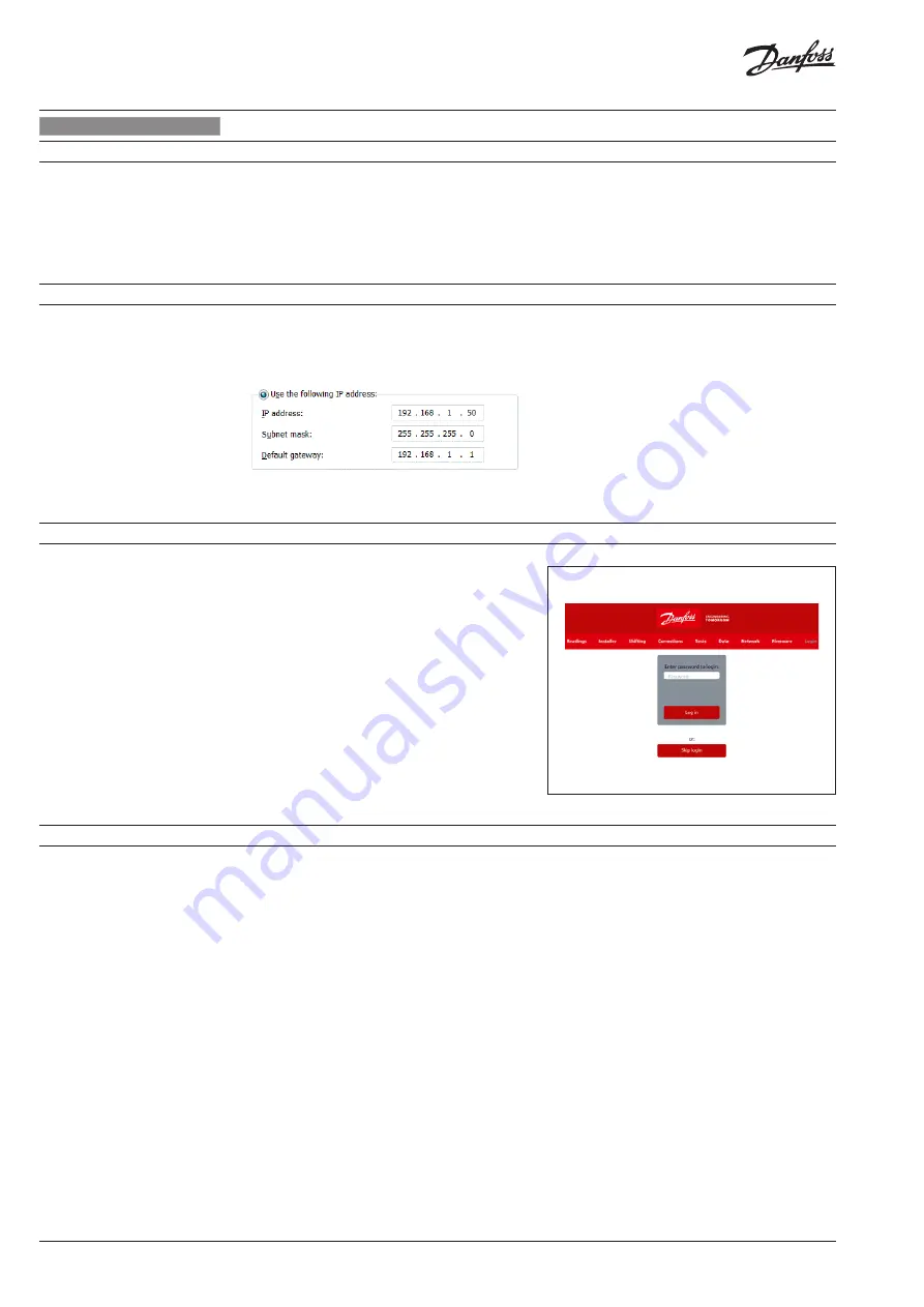
Launch your browser from a computer or 

wireless device that is connected to the CCR3+. 

Tap the IP address into web browser window: 

1. Wi-FI access: Type 192.168.1.10 into Web 

Browser 

2. LAN connection: Type 192.168.1.100 into Web 

Browser 

CCR3+ application will open. 

For 1st login enter password »

admin1234

« 

Important: 

Change of password to secure any 

unauthorized interaction from 3rd parties.

Note: 

You can Skip login for access to data only 

in CCR3+ (reading, overview only).

When the setup and is complete, the reading 

display will be shown on the screen.

The CCR3+ App screen has a dashboard that 

offer plenty of status overview, basic and 

advanced settings. The manufacturer reserves 

the right to change Firmware in production to 

improve handling and  functionality. An up - to 

- date list of settings for the given firmware is 

available on the Danfoss website.

New settings can automatically upgrade 

according to guidelines in instruction.

• 

Readings:

 Informations about basic settings, 

device status, current time and date, storage 

capacity

• 

Installer:

 Advanced and service settings

• 

Shifting:

 Shift return temperature

• 

Corrections:

 Temperature sensor calibration 

settings

• 

Tests:

 Device outputs testing tool

• 

Data:

 Access to Data log file

• 

Network:

 BMS and IP/TPC settings

• 

Firmware:

 Firmware upgrade tool

• 

Login:

 Login option

Summary of Contents for CCR3+

Page 1: ...Danfoss 2019 02 VI GM A2 02 1 ENGLISH CCR3 Controller www danfoss com CCR3 Controller Operating Guide...

Page 2: ...2 Danfoss 2019 02 VI GM A2 02 CCR3 Controller Fig 1 Installation with CCR3 Controller up to 20 risers loops Fig 2 Installation with CCR23 Controller Master and CCR Slave Unit more that 20 risers...

Page 3: ...bus RS 485 C O1 O4 C common port dedicated to outputs O1 O4 O1 output Alert Broken Sensor O2 output Alert Low Temp O3 output Alert High Temp O4 output not in use C V1 4 C common port dedicated to actu...

Page 4: ...efined output O2 Defined output O3 Defined output O4 Risers temperature sensors S1 S20 Type of sensor PT1000 B1 Def input B1 B2 Def input B2 B3 Def input B3 CCR3 Master Wiring diagram S0 main sensor P...

Page 5: ...it Connector port Description 0V 24VDC 0V ground power supply 24 VDC power supply C V21 24 C common port dedicated to actuators V21 V24 outputs to actuators C V24 28 C common port dedicated to actuato...

Page 6: ...e 30 C Transport temperature 10 60 C IP rating IP 20 Power supply 24 VDC Power consumption Controller only 1 10 VA Power consumption Slave Unit only 1 3 VA Weight 0 3 kg Installation DIN rail 35 mm 1...

Page 7: ...connected to the controllers input and output connectors 1 Set all parameters on the controller 2 Make sure that there is no external voltage on the temperature sensor plugs 3 Make sure that the volta...

Page 8: ...password admin1234 Important Change of password to secure any unauthorized interaction from 3rd parties Note You can Skip login for access to data only in CCR3 reading overview only When the setup and...

Page 9: ...6 1 open valve output closed to C powered up taking PWM into account 0 valve closed valve output closed to C powered down taking PWM into account Valve is 1 Open if PWM min Valve PWM max 9 Valve valve...

Page 10: ...for Output which Over temperature or Broken Sensor Higher the value longer the reaction time alarm signal Factory setting 0 min 33 Alarm diff temp Set upper lower deviation temperature counted from R...

Page 11: ...ed Factory setting Odd 57 Modbus address Unit Address for Mobus RTU RS485 Factory setting 1 58 LAN IP address The IP address that the router assigned to this device when it joined the network This num...

Page 12: ...s reset to admin00X where x is the number of BT blue LED blinks Reset the setting only Go to firmware menu and click on Return Defaults Reset password only but not change other parameters Go to firmwa...

Page 13: ...sed B4 open closed RTC year RTC month RTC day RTC hour RTC minute B1 open closed B2 open closed B3 open closed S0 temp Ret Set Temp Status alert from 300 to 331 300 301 302 303 304 305 306 307 308 309...

Page 14: ...14 Danfoss 2019 02 VI GM A2 02 CCR3 Controller...

Page 15: ...Danfoss 2019 02 15 VI GM A2 02 CCR3 Controller...

Page 16: ...VI GM A2 02 16 Danfoss DHS SRMT SI 2019 02 CCR3 Controller...

Reviews: