background image

W E B S T A T I O N    M a n u a l   P a g e  12

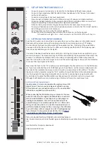
MIC / LINE INPUT MODULES 1-2


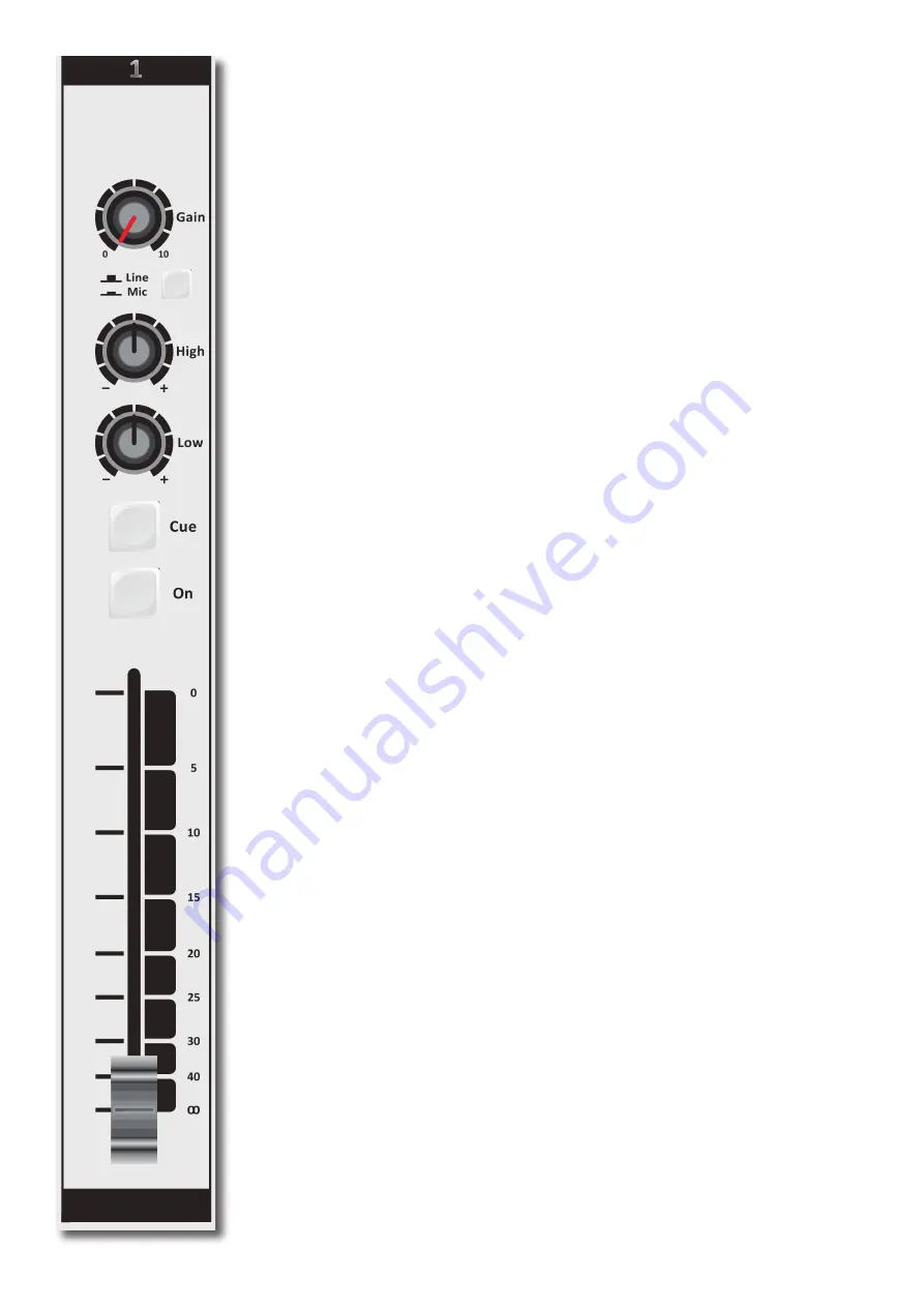
The input modules switches & controls of the Webstationmixer have the following functions: 


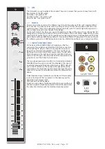
Each of Modules 1 and 2 have two selectable inputs. The two types of inputs consist of a Micro

-

phone input and a stereo line input. In the lower Mic switch position, the module is a normal 

mono module. When the Mic is switched off (up position), you also have a stereo line level input 

to feed the stereo PROGRAM buss, CUE buss and Voice Tracking buss.


5.1 

GAIN

With the gain control (the first control knob below the modules number), the source input level 

can be adjusted to the required internal mixer level. This control adjusts both the Mic input and 

the stereo line inputs with the same control depending on the switch position. 


5.2 

STEREO LINE

The stereo line input is a high impedance input ( >10 kOhm) for connecting the stereo line level 

outputs of devices such as CD players/MP3 players etc.


5.3 

MIC


The Mic input has a balanced XLR input connector with 48 volt phantom powering for condenser 

mikes.

The Mic-pre circuitry uses the latest technology studio-class components as used in high end 

recording consoles. We use the That 1510 Mic-pre which is highly acclaimed for its low noise/dis

-

tortion and transparent audio. The low-noise design and excellent phase spec that D&R is known 

for is integrated throughout the Webstation which results in a phase coherent signal path. Using 

balanced microphones & cables allows for the quietest and high quality audio signals through

-

out your Webstation mixer. You can use standard balanced Mic cables available at any pro audio 

dealer or music store. The Webstation uses chassis-mount female XLR type Mic input connectors. 

Any standard pro audio Mic cable will fit into this female XLR connector.


5.4 

EQUALIZER


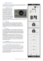
Each module has a stereo two band equalizer to control the high and low frequencies individu

-

ally. The D&R designers used carefully chosen frequencies in the equalizer circuitry to enhance 

the Mic input as well as the stereo line input.


5.5 

CUE/COMMUNICATION BUSS


Below the LOW EQ potmeter is the stereo CUE switch (Pre Fade Listening).

This switch allows you to check the signal before you raise your channel fader up and mix 

it with other signals in the mixer. Another smart function is that this CUE bus can be used 

for communication. If you push a DJ’s Cue (let’s say channel one) and if you then push the 

Telco(VoIP) Cue (located in the TELCO(VoIP) module) , the DJ as well as the caller can hear each 

other outside the broadcast and even you, sitting behind the desk on the monitor speakers. 

Note: 

Levels need to


be carefully set to avoid feedback and overdrive of circuits. 

The Cue switch 

also sends out HID(Human Interface Device)  signal over USB that can be programmed to do 

specific functions in your play-out system.


5.6 

ON


The ON switch is used to pass on the audio. The ON switch also sends out HID signal over USB that 

can be programmed to do specific functions in your play-out system. In the Control section of the 

manual we will explain how.


5.7 

VOICE TRACK BUSS


The ON switch is ALSO used to route an input signal from module 1-2 to the Voice track buss.


Push the ON switch a little bit longer and the audio will be removed from the Program buss and as

-

signed to the Voice track buss, as a result the ON switch will blink. The Voice track signal Is routed 

to USB-3 for further processing in your play-out system.

5.8 

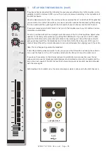
FADER

Final audio level control is the high quality, 100 mm long throw N-Alps channel fader that send out 

a control voltage to the internal stereo VCA. The control voltage is also used to detect when the 

fader is moved up and can send out a pulse for fader start purposes. This control voltage activates 

the start circuitry that can be assigned to one of the two GPO connectors.

A software page (as already seen on the next page) will be shown further in this manual to cus

-

tomize the Webstation to your needs with instructions how to do that.

Summary of Contents for WEBSTATION

Page 1: ...W E B S T A T I O N M a n u a l P a g e 1 MANUAL v1 02 D R Electronica B V Rijnkade 15B 1382GS Weesp The Netherlands Phone 31 0 294 418014 Fax 31 0 294 416987 Website http www d r nl E Mail mail d r nl ...

Page 2: ...12 5 3 MIC 12 5 4 EQUALIZER 12 5 5 CUE COMMUNICATIONS BUSS 12 5 6 ON 12 5 7 VOICE TRACK BUSS 12 5 8 FADER 12 5 9 INPUT CONNECTOR 13 5 10 INSERT 13 5 11 MICROPHONE INPUT 17 6 USB LINE INPUT MODULES 3 4 5 14 6 1 GAIN 14 6 2 STEREO LINE 14 6 3 USB 14 6 4 CUE COMMUNICATION BUSS 14 6 5 ON 14 6 6 FADER 14 6 7 SETTING UP THE USB MODULES 14 6 8 USB OUTPUTS 14 6 9 SETTING UP THE MODULES 15 7 VOIP LINE INPU...

Page 3: ...6 12 4 6 microphone 26 12 5 master settings 27 12 5 1 silence detection 27 12 6 read write configuration from to console 28 12 6 1 store internal 28 12 7 Configuration Presets 28 12 7 1 Create Presets 28 12 7 2 load preset 28 13 WEBSTATION METERS 29 13 1 Introduction 30 13 1 1 analog and digital clock 30 13 1 2 ppm meters 30 13 1 3 silence detaction 30 13 1 4 mic on timer 30 13 1 5 settings 31 13 ...

Page 4: ... confident that you will be using the webstation mixer for many years to come and wish you much success We value suggestions from our clients and would be grateful if you could email us with your comments when you are familiar with the webstation mixer We learn from the ideas and suggestions of customers like you and appreciate your time taken to eventually do this And we always appreciate nice st...

Page 5: ...ation interface between the Webstation console and other applications i e Webstation Meters The application runs at the background and connects to the console automatically when its USB main port is connected to the PC 1 Double click on Webstation Control vx x x x Setup exe 2 Follow the installation instructions on the screen 3 If installation was successful you will see the Webstation Control ico...

Page 6: ...when clicked with a mouse or touch screen The NONSTOP indicator can also be used as remote control by clicking on it 1 Double click on Webstation Meters vx x x x Setup exe 2 Follow the installation instructions on the screen 3 Double click on the icon on your desktop to run the application 4 Press the settings symbol in the upper right corner 5 Set remote host to 127 0 0 1 6 Check the Use defaults...

Page 7: ...ouble click on the icon on your desktop to run the application 4 Press the Options Communication from the menu bar 5 Set remote host to 127 0 0 1 6 Check the Use defaults checkbox and press OK 7 Press READ to read configuration settings from the console 1 4 Webstation Voip Webstation Voip is an application which let you answer or end calls from a voip application only Skype supported at the moment...

Page 8: ...ware Updatetool vx x Setup exe 2 Follow the installation instructions on the screen 3 Double click on the icon on your desktop to run the application 4 Make sure the console is in bootloader mode Power off the console Press and hold on the CONNECT button located in channel 8 VoIP Power on the console Release CONNECT button 5 Select D R Webstation from the device list 6 Select the firmware file hex...

Page 9: ...IP send control for outgoing level Stereo CUE switch for pre fade listening ON switch 100 mm professional N Alps fader with fader start Stereo VCA fader control 2 4 MASTER SECTION Master controls for Phones CRM CRM section with Cue Reset and Auto Cue NON STOP switch routes module 3 USB stereo input di rectly to the main program Cinch connectors 12 free programmabled control switches for music play...

Page 10: ...W E B S T A T I O N M a n u a l P a g e 10 3 SIGNAL FLOW ...

Page 11: ...l info from the programmable Control section plus the Clock and meter information This USB feature will also allow you to connect to the Internet via your computer for Live streaming of audio to the Internet Module 6 VoIP has as extra a stereo line input for external analog Hybrids and cleanfeed outputs to drive these external Hy brids incase a VoIP connection is not available or not yet installed...

Page 12: ...requencies individu ally The D R designers used carefully chosen frequencies in the equalizer circuitry to enhance the Mic input as well as the stereo line input 5 5 CUE COMMUNICATION BUSS Below the LOW EQ potmeter is the stereo CUE switch Pre Fade Listening This switch allows you to check the signal before you raise your channel fader up and mix it with other signals in the mixer Another smart fu...

Page 13: ... of the stereo cable to the tip of the other mono jack Now insert the stereo jack into the Webstation s insert and connect the mono jack that produces a hum when the tip is touched by your finger and the related channel fader is open into the processors output The other mono jack should be inserted into the processors input In case your processor has XLR inputs connect the tip of the stereo jack t...

Page 14: ... 5 ON The ON switch also sends out HID signal over USB that can be programmed to do specific func tions in your play out system In the Control section of the manual we will explain this how 6 6 FADER Final audio level control is the high quality 100 mm long throw N Alps channel fader that send out a control voltage to the internal stereo VCA The control voltage is also used to detect when the fade...

Page 15: ...audio hardware After establishing a connection there is no need to download drivers or performing complicated setup routines just plug in the USB cable to your Windows or Mac computer and start tracking or playing a maximum of 3 stereo channels at the same time If you want to know more about USB try this link http en wikipedia org wiki Audio_Stream_Input Output If you are already familiar with dig...

Page 16: ...upport There are some SKYPE software settings you need to go through before this is working with your console For some usefull instructions go to https support skype com nl faq FA34541 een perfect skype gesprek voeren Dutch instruction video but I am sure there is one in your own language or in English of course 7 3 GAIN With the GAIN control the source level is adjusted to the internal mixer leve...

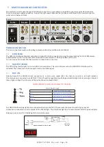
Page 17: ... 10 position as your unity gain position 7 10 INPUT CONNECTORS On the back of the WEBSTATION VoIP module you find four connectors Two unbalanced stereo line RCA Cinch connectors for connecting CD players iPods or any play back devices as long as they are line level equipment The level can be set us ing the gain control to match most source levels The left RCA Cinch connector is the right input and...

Page 18: ... outputs and CUE from any input module or from the Master section Normally the left right output is heard until a Cue switch is activated from anywhere in the console By pressing a CUE switch you will hear the associated signal rather than the left right sig nal in the PHONES The software meter application switches accordingly with this action We advise you to use headphones with an input impedanc...

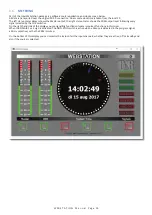
Page 19: ... stereo meter shows the CRM output level following every signal selected by the CUE switches On the right hand side of the display you see signalling functions of some important functions in this mixer When the ON AIR 1 or 2 sign is activated The NON STOP switch is active when a Silence is detected in the program signal a Mic is on active or the the CRM is muted On the bottom of this display you c...

Page 20: ...ogram outputs are on two RCA Cinch connectors This is also the case when the NON STOP ON AIR switch is activated Then these main Cinch connectors carry the USB 3 signal 9 3 MIC ON Directly beneath the MASTER cinch connectors is a stereo jack socket Mic On that can control a red light indicator This stereo jack is connected to an OPTO FET This FET switch is capable of controlling external Red light...

Page 21: ...0 dBu output level Re lease the CUE switch so the metering can now read the output signal again Now push the ON button to connect the input signal to the fader Now move the fader to the 10 position screened alongside the channel faders or to the 0dB indica tor if you have cancelled the extra 10dB fader gain in the software Further volume adjustments can be made on the equipment your signal is send...

Page 22: ... call is picked up by pushing the CONN button If you want to hear the caller press the CUE button in the same channel to listen to the incoming call Adjust the Gain control to get a good input level from the telephone line To be able to talk to the caller press CUE in your DJ channel Adjust the VoIP send potentiometer to increase or decrease the outgoing level to the caller Note This is all happen...

Page 23: ...e 23 12 WEBSTATION CONFIGURATION MANAGER Configuration Manager User Manual VERSION 1 0 790 0 D R Electronica B V Rijnkade 15B 1382GS Weesp The Netherlands Phone 31 0 294 418014 Fax 31 0 294 416987 Website http www d r nl E Mail mail d r nl ...

Page 24: ...anywhere on the network like Webstation Configuration Manager In order to use Webstation Configuration Manager follow the steps below 1 Connect the USB main port of the Webstation to your PC with the supplied USB cable 2 Install configure and run the Webstation Control application on this main PC 3 Run Webstation Configuration Manager on any PC in the network or from your home 12 3 Communication P...

Page 25: ...ing the console Using this function while a power outage occurs prevents silence on air if no person is in the studio to re activate the module 12 4 2 Auto CUE Reset When the CUE switch of a module in the console is activated also called PFL the selected source LINE or MIC USB VoIP will be routed to the CUE buss To deactivate a module from the CUE buss you can press again the CUE switch The Auto C...

Page 26: ...tings are only available for modules 1 and 2 MIC modules In order to prevent feedback from a microphone in the Control Room the functions CRM Mute and CRM Auto Cue AutoDeacti vate can be enabled CRM Mute Mute CRM buss when the module is active MIC selected CRM Auto Cue AutoDeactivate Deactivate the Auto Cue CRM function when cue ing module MIC selected 12 4 6 Microphone These settings are only ava...

Page 27: ...ft right stereo in the event of the signal going below the threshold 40 0dB after a given interval In this situation the unit will go into ALARM state and switches the nonstop source to the master output The Interval Unit can be set to seconds or minutes The red flashing nonstop switch on the console indicates the alarm state The silence alarm can be reset by pressing the nonstop switch which will...

Page 28: ...active but not saved internally The configuration is lost after a power off 12 6 1 Store Internal The Store Internal button stores the current configuration in the console to persistent memory EEPROM This means the con figuration is still active after a power off A warning will be prompted to make sure you want to overwrite the internal saved con figuration 12 7 Configuration Presets Webstation Co...

Page 29: ... n u a l P a g e 29 13 WEBSTATION METERS Meters User Manual VERSION 1 1 205 0 D R Electronica B V Rijnkade 15B 1382GS Weesp The Netherlands Phone 31 0 294 418014 Fax 31 0 294 416987 Website http www d r nl E Mail mail d r nl ...

Page 30: ...ferent ranges and read outs Based on the most used scale the following type is used IEC 60268 10 Type I DIN scale This scale ranges from 50 to 5dB 13 1 3 Silence detection Since continuous radio is important for a radio station the Webstation is equipped with a built in software silence detector which guards presence of audio signal on the master output If no sound is present for a specified time ...

Page 31: ...he Webstation Control application is not running or the Webstation console is disconnected 13 1 7 Console signals At the right side Webstation Meters contains a set of console signals indicating internal states of the console PHONE Informs you about an incoming call on module 6 VoIP ON AIR 1 2 Configurable Logical busses Can be attached to a GPO for example NONSTOP Used as indicator as well as a r...

Page 32: ...N switches and can therefore behave as remote of the hard ware switches Clicking on the icons results in toggling the ON state NOTE If the icon flashes the module is in voicetrack mode 13 1 10 Source select Each module can select between LINE and MIC USB VoIP source depending on the module Additional to showing the ON switch state the currently selected source for each module will be shown in the ...

Page 33: ...ing media and want to experiment before rolling it out to a large audience The Helix Server Basic is free to download http www realnet works com products services free helix products aspx Quicktime Streaming Server Apple com says Whether you are looking to add streaming media to your web site deliver distance learning or provide rich content for your mobile subscribers Mac OS X Server has all of t...

Page 34: ... compliant with USB 2 0 playback and record mode 3x Stereo in and Main stereo Voice Track or VoIP signal out HID Functions Volume Mute Control USB CONTROL SECTION 12 free assignable illuminated switches plus encoder based on the HID protocol MIC ON Stereo jack Tip is a change over contact between sleeve and ring NOT FOR 110 220 VOLT SWITCHING It can only switch 24V 50mA max OUTPUTS Left Right 0 dB...

Page 35: ...382 GS City WEESP Country The Netherlands Phone 0031 0 294 418 014 Fax 0031 0 294 416 987 Website http www d r nl E mail mail d r nl 15 3 SUMMARY We hope this manual has given you sufficient information to use this new Webstation mixer in your studio If you require more info please contact your local dealer or send us an email at mail d r nl and we will answer your email within 24 hours during wee...

Page 36: ...ment for reliability in the HIGH VOLTAGE section 15 7 CAUTION Never remove any panels or open this equipment No user serviceable parts inside Equipment power supply must be grounded at all times Only use this product as described in the user manual or brochure Do not operate this equipment in high humidity or expose it to water or other liquids Check the AC power supply cable to assure se cure con...

Page 37: ... g e 37 D R Electronica B V Rijnkade 15B 1382GS Weesp The Netherlands Phone 31 0 294 418014 Fax 31 0 294 416987 Website http www d r nl E Mail mail d r nl T h e p l a c e w h e r e a l l m i x e r s a r e d e s i g n e d a n d b u i l d ...

Page 38: ...W E B S T A T I O N M a n u a l P a g e 38 ...

Reviews: