W E B S T A T I O N M a n u a l P a g e 11
4
WEBSTATION BACKPANEL
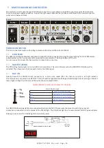
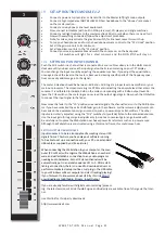
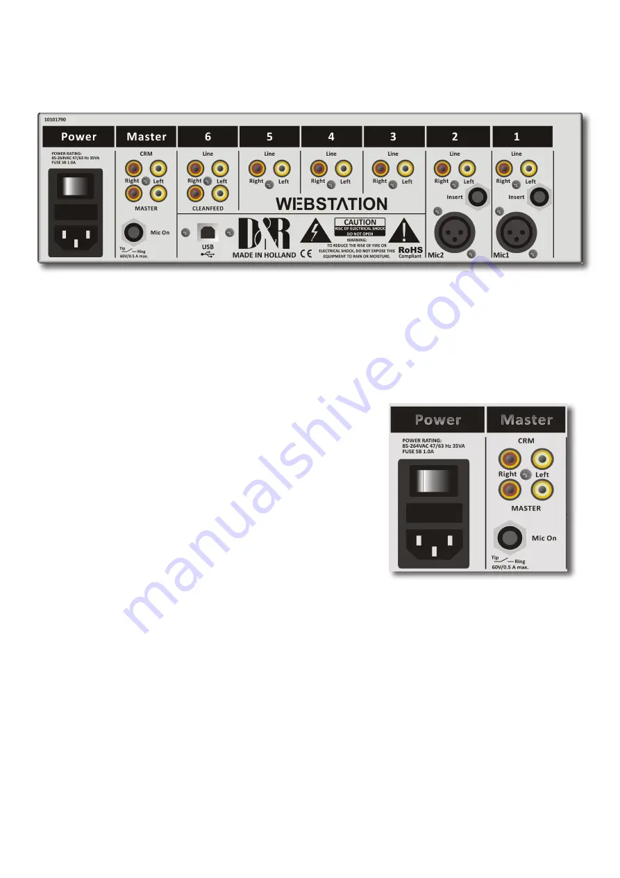
The back panel shows all the in and output connectors to interface with your other equipment.
The first two of modules 1-2 MIC/LINE modules on the right have balanced XLR mic inputs with a mic insert for voice processing.
Two cinch connectors accept line level left/right input signals.
Modules 3-4-5 are the USB inputs that are fed from a built in USB HUB that accepts and sends stereo sends signals to a con-
nected PC where a music play-out systems could be active.
There are also stereo line inputs available on Cinch connectors per input 3-4-5. (6)
The module backpanel also houses the USB connector for both the audio and the VoIP connection.
The USB connector carries all the 4 stereo audio signals to and from the PC (for both Windows & Macintosh computers)
as well as the Play-out systems control info from the programmable Control section plus the Clock and meter information.
This USB feature will also allow you to connect to the Internet via your computer for “Live” streaming of audio to the Internet.
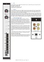
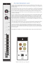
Module 6 (VoIP) has as extra a stereo line input for external (analog) Hybrids and cleanfeed outputs to drive these external Hy
-
brids incase a VoIP connection is not available or not yet installed. This external Hybrid nees to be returned on the line inputs of
the same VoIP channel.
4.1
MASTER CONNECTORS
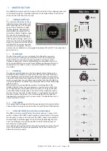
The master section houses all the in and outputs of the controls on the front
panel that will be discussed in more detail in other chapters.
Most of the functions are self explanatory, such as master right and
left Cinch connctors and CRM cinch connectors for your monitoring.
Below the 4 Cinch connectors you see a stereo jack that is called Mic On.
Here you connect your On-AIR light on the tip and ring to show your micro
-
phone is active.
Worth mentioning is the heavy duty external power supply that accepts voltages
between 85 en 260 volts AC 50/60Hz.


