36
60
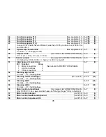
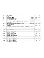
Brake sections
1 or 2
0, 1
(0)
61
Shuntig gear speed
(As CV05)
0
– 127
(63)
62
Shunting gear deceleration
(As CV03)
0
– 255
(1)
63
Starting delay speed step 1
(See CV124)
Each 100 ms, 0 = deacitvated
0
– 250
(0)
64
Function mappimg F2(r)
(See supplement 1)
In case CV64 should have a different value than CV36, you must set CV36 first
and then CV64
0
– 255
(8)
65
Maximum speed step in two-part brake sections
(See CV60)
Only with brake diode
0
– 127
(12)
66
Forward-trim
0 = deactivated, smaller 128 = reduction, greater 128 = enhancement of the speed
0
– 255
(0)
95
Backward-trim
(As CV66)
0
– 255
(0)
105
User identification 1
0
– 255
(0)
106
User identification 2
0
– 255
(0)
112
Speed reduction analog
(Not relevant to FH05B/FH18A/FH22A/PD05A)
0 = small reduction
… 31 = strong reduction
0
– 31
(15)
113
Switch-off function for LV
Bit 0 = F1 ... bit 7 = F8
0
– 255
(0)
114
Switch-off function for LR
Bit 0 = F1 ... bit 7 = F8
0
– 255
(0)
115
Switch-off function for AUX1
Bit 0 = F1 ... bit 7 = F8
0
– 255
(0)
116
Switch-off function for AUX2
Bit 0 = F1 ... bit 7 = F8
0
– 255
(0)
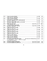
117
Timer for switch-off AUX1
Each 100 ms, 0 = deactivated
0
– 250
(0)
118
Timer for switch-off AUX2
Each 100 ms, 0 = deactivated
0
– 250
(0)
Summary of Contents for DH05C
Page 68: ...68 Blank page for your notes...

