


Standalone MMC Hardware Manual
113
Danaher Motion
version 15.1
Standalone Digital MMC Control
•
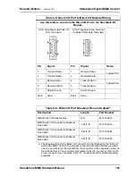
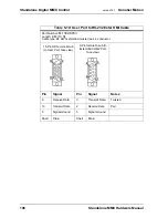
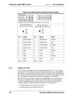
The available Digital Link Port to Digital Drive cables are described in
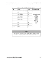
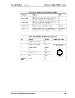
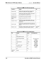
Table 5-19: Digital Link Port Pin Descriptions
Function
Notes
Pin
Receive Data +
Receives data from connected drives.
3
Receive Data -
Receives data from connected drives.
6
Transmit Data +
Transmits data to connected drives.
1
Transmit Data -
Transmits data to connected drives.
2
Shield Ground
Provides a path for shield current through the
chassis to an external single point ground.
Shell
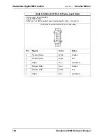
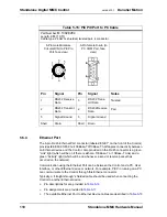
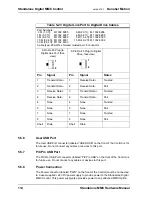
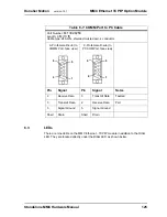
Table 5-20: Digital Link Port Pin Assignments
Pin
Signal
In/Out
Pin Sequence
1
Transmit Data +
Out
RJ-45
2
Transmit Data -
Out
3
Receive Data +
In
4
Termination Resistors
a
a. Pins 4, 5, 7, and 8 are tied to termination resistors on the Control. Standard
Ethernet cables contain 8 wires. The Control only uses 4 of these wires as
shown. Connecting the 4 unused wires to the Control pins 4, 5, 7, and 8, (as will
be done in a standard Ethernet cable) reduces noise that can be induced from
the unused wires to the Transmit and Receive wires.
In
5
Termination Resistors
In
6
Receive Data -
In
7
Termination Resistors
In
8
Termination Resistors
In
Connector
Shell
Shield
In
1
8
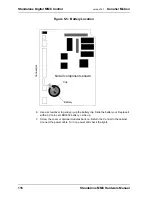
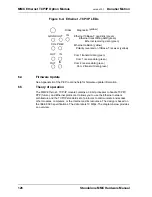
TRANSMIT
LINK
B1 (2,3,4)
light
light
Summary of Contents for Standalone MMC
Page 4: ......
Page 8: ...8 Standalone MMC Hardware Manual Table of Contents version 15 1 Danaher Motion ...
Page 94: ...94 Standalone MMC Hardware Manual Standalone MMC Control version 15 1 Danaher Motion ...
Page 169: ...Standalone MMC Hardware Manual 169 Danaher Motion version 15 1 CE and EMC Guidelines ...
Page 170: ...170 Standalone MMC Hardware Manual CE and EMC Guidelines version 15 1 Danaher Motion ...
Page 171: ...Standalone MMC Hardware Manual 171 Danaher Motion version 15 1 CE and EMC Guidelines ...
Page 172: ...172 Standalone MMC Hardware Manual CE and EMC Guidelines version 15 1 Danaher Motion ...


