


108
Standalone MMC Hardware Manual
Standalone Digital MMC Control
version 15.1
Danaher Motion
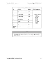
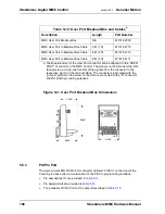
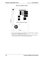
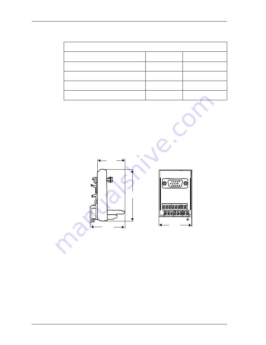
Figure 5-3: User Port Breakout Box Dimensions
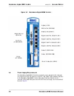
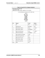
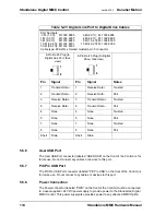
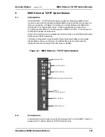
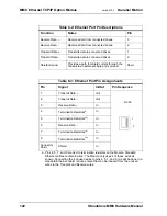
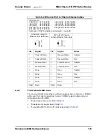
5.5.3
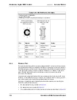
PiCPro Port
The 6-pin circular DIN PiCPro Port connector (labeled “PiCPro” on the front of the
Control) provides serial communication for the PiCPro programming interface.
•
Pin descriptions for are provided in
•
Pin assignments are provided in
•
The available PiCPro Port to PC cable is described in
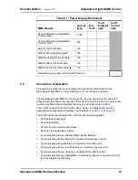
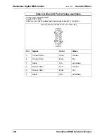
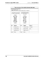
Table 5-12: User Port Breakout Box and Cables
a
a. The Breakout Box for the User Port connector can be attached to the “USER
PORT” connector on the MMC Control. The pinouts on the terminal strip inter-
face provide a one-to-one transfer of the signals from the connector to the
respective pin(s) on the terminal block. The connector pins marked with the
“ground” symbol on the screw connector are connected to the “D” connector
shell for shield grounding purposes.
Description
Length
Part Number
MMC User Port Breakout Box
N/A
M.1016.2530
MMC User Port to Breakout Box Cable
.3 M (1 ft)
M.1016.2715
MMC User Port to Breakout Box Cable
.6 M (2 ft)
M.1016.2716
MMC User Port to Breakout Box Cable
.9 M (3 ft)
M.1016.2717
1.750”
2.250”
3.000”
1
9
2.250”
8
15
Summary of Contents for Standalone MMC
Page 4: ......
Page 8: ...8 Standalone MMC Hardware Manual Table of Contents version 15 1 Danaher Motion ...
Page 94: ...94 Standalone MMC Hardware Manual Standalone MMC Control version 15 1 Danaher Motion ...
Page 169: ...Standalone MMC Hardware Manual 169 Danaher Motion version 15 1 CE and EMC Guidelines ...
Page 170: ...170 Standalone MMC Hardware Manual CE and EMC Guidelines version 15 1 Danaher Motion ...
Page 171: ...Standalone MMC Hardware Manual 171 Danaher Motion version 15 1 CE and EMC Guidelines ...
Page 172: ...172 Standalone MMC Hardware Manual CE and EMC Guidelines version 15 1 Danaher Motion ...


