background image

TSM-0064 - TE27/32 4-Speed LD with Full Flow Control Valve Service Manual                           

Dana Holding Corporation

      10

Automatic Calibration Procedure

HEATING UP THE TRANSMISSION BY USING THE ‘HEAT’-MODE

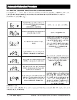
The ‘HEAT’-mode allows to select forward / reverse while the parking brake is activated, without forcing neutral and will 
disable the inching and declutch function. During the heat mode the highest gear is forced – even when the shift lever is 
in a lower gear. This combination allows the driver to heat up the transmission by going into stall.

‘HEAT’-mode can be activated in the same way automatic calibration mode is entered (see “ENTERING AUTOMATIC 
CALIBRATION MODE”, on page 8). Once “tran” is displayed on the screen, press the M-button once to go into the 
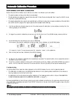
“HEAT”-mode. The APC200 will display:

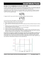
To trigger the ‘HEAT’-mode, push the S-button. The APC200 will display the sump temperature:

This means the actual sump temperature of the transmission is 20°C.

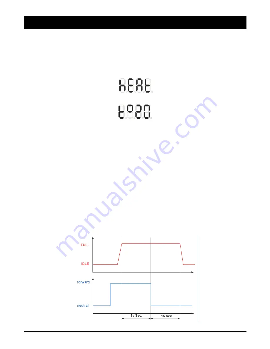
Perform the following steps in order to heat up the transmission:

1.

Make sure the parking brake is active and works properly.

2.

Put the transmission in forward by selecting forward with the shift lever and then accelerates the engine to full throt-
tle.

3.

Keep the engine at full throttle for about 15 seconds and then put the gearbox in neutral by selecting neutral with 
the shift lever. Keep the engine at full throttle!

4.

Keep the gearbox in neutral at full engine throttle for about 15 seconds again.

5.

Release the throttle pedal and decelerate the engine to idle.

6.

Go back to point 2 and repeat until the APC200 display shows a temperature above 140°F [60°C]. When the tem-
perature is above 140°F [60°C], the temperature indication on the display starts blinking. Now switch to automatic 
calibration by pressing the M-button several times – until the APC200 displays “tran”.

During this warm up procedure, it is possible for the converter out temperature of the transmission to exceed the maxi-
mum limit. This is a consequence of heating up the transmission using this quick procedure. When this occurs, the 
engine speed will be limited to half throttle when the APC200 has engine control or forcing neutral when the APC200 
has no engine control. To solve this, simply leave the transmission in neutral for a minute and throttle the engine to 
around 1300 rpm. This will allow the heat in the converter to be evacuated. After one or two minutes, resume the heat-
ing up procedure if the transmission temperature has not reached 60°C yet.

Summary of Contents for SPICER TE27

Page 1: ...Service Manual PowershiftTransmission TE27 TE32 4 Speed Long Drop with Full Flow ControlValve TSM 0064 August 2012 80 1070 Rev 5 12 2014 ...

Page 2: ......

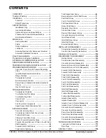
Page 3: ...rth Clutch Shaft Assembly 63 Forward Clutch Shaft Group 65 Third Clutch Shaft Group 67 Third Speed Gear Group 69 Reverse Second Clutch Shaft Group 71 First Shaft Group 73 Fourth Clutch Shaft Group 75 First Speed Gear Group 77 Output Shaft Group 79 Regulator Valve Group 81 Control Valve Group 83 Remote Filter Adapter Group 85 Converter Housing Cover Group 87 Input Flange Group 89 Idler Shaft Gear G...

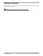
Page 4: ...vice Manual TOWING OR PUSHING Before towing the vehicle be sure to lift the driven axle wheels off the ground or disconnect the driveline to avoid dam age to the transmission during towing NOTE Because of the design of the hydraulic system the engine cannot be started by pushing or towing ...

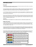
Page 5: ...nd or property damage the following instructions must be carefully observed Proper service and repair are important to the safety of the service technician and the safe reliable operation of the machine If replacement parts are required the part must be replaced with a Dana specified replacement part NEVER use a replacement part of lesser quality The service procedures recommended in this manual a...

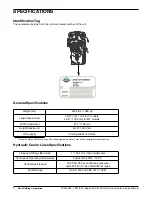
Page 6: ...maximum 39 8 1011 mm for T models 46 8 1189 mm for MT models Width maximum 27 7 703 mm Height maximum 49 6 1260 mm Oil Capacity 7 9 US gallons 30 liters Without cooler and hydraulic lines Consult equipment operator s manual for complete system capacity Lines and Fittings Minimum 1 25 4 mm internal diameter Continuous Operating Temperature Ambient to 248 F 120 C Continuous Pressure 406 PSI 28 bar c...

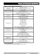
Page 7: ... Pump Flow At 1900RPM 31 5 GPM 119 3 l min minimum Lube Pump Flow At 2170 RPM selective lube 12 5 GPM 47 2 l min minimum Clutch Pressure 1st clutch Port 41 2nd clutch Port 42 3rd clutch Port 43 4th clutch Port 44 Forward clutch Port 45 Reverse clutch Port 46 At 2200 RPM 297 3 PSI 20 5 bar minimum with 1st clutch activated Filter Bypass Valve Set at 59 4 65 2 PSI 4 1 4 5 bar Lube Pressure Port 34 5...

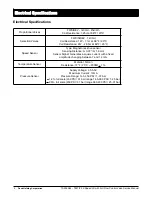
Page 8: ...8 F 20 C Coil Resistance 24V 28 5 at 68 F 20 C Speed Sensor Type Magneto resistive sensor Sensing Distance 0 0 07 0 1 8 mm Sensor Signal Generates a square current with a fixed amplitude changing between 7 and 14 mA Temperature Sensor Material Silicon Resistance 77 F 25 C 2000 1 Pressure Sensor Supply Voltage 4 5 5 5V Maximum Current 10mA Pressure Range 14 5 450 PSI 1 31 bar 1 2 full scale 450 PSI...

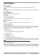
Page 9: ...will result in accelerated deterioration or contamination Judgement must be used to determine the required change intervals for extreme conditions Every 1000 hours Change oil filter element Drain oil at 150 200 F 65 93 C and refill system as follows 1 Drain transmission 2 Remove and discard filter 3 Install new filter 4 Refill transmission to FULL mark 5 Run engine at 500 600 RPM to prime converte...

Page 10: ...hydraulic lines should be removed from machine for clean ing 3 Replace oil filter element 4 The oil cooler must be thoroughly cleaned The cooler should be back flushed with oil and compressed air until all foreign material has been removed Flushing in direction of normal oil flow will not adequately clean the cooler If necessary cooler assembly should be removed from machine for cleaning using oil...

Page 11: ...ure which is able to optimize the shift quality of the transmission An automatic calibration has to be done When the vehicle is build at the OEM Every 2000 hours of transmission operation When an overhaul of the transmission is done When the transmission is repaired When the APC200 is replaced ENTERING AUTOMATIC CALIBRATION MODE The automatic calibration mode is entered by pressing the S button on...

Page 12: ...le M1 stands for mode 1 of the calibration 4 When all clutches have been calibrated the APC200 displays 5 At this point the automatic calibration has completed successfully The normal duration of a complete transmission calibration is around 15 minutes 6 To exit the automatic calibration mode switch off the vehicle ignition key Make sure that the APC200 has powered down wait for 2 seconds Now rest...

Page 13: ...r and then accelerates the engine to full throt tle 3 Keep the engine at full throttle for about 15 seconds and then put the gearbox in neutral by selecting neutral with the shift lever Keep the engine at full throttle 4 Keep the gearbox in neutral at full engine throttle for about 15 seconds again 5 Release the throttle pedal and decelerate the engine to idle 6 Go back to point 2 and repeat until...

Page 14: ... parking brake is ON and working properly If this is already the case keep the machine at standstill by using the brake Once the machine has been stopped the APC200 will ask the driver to shift to FORWARD before continuing the calibration Engine RPM is to low according to the limit that is necessary for calibration When during the automatic transmission calibration the temperature becomes to low t...

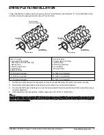
Page 15: ... to 30 37 lbs ft 40 50 N m NOTE Assembly of all plates must be completed within 15 minutes from when screws are installed If a screw is removed for any reason it must be replaced The adhesive left in the tapped holes must be removed with the proper tap and cleaned with solvent Dry the hole thoroughly and use a new screw for reinstallation Each kit includes 2 Intermediate Drive Plates 1 Drive Plate...

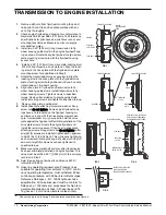
Page 16: ...d on the flywheel housing cir cumference in line with the drive plate screw access hole A screwdriver or pry bar used to hold the drive plate against the flywheel will facilitate installation of the drive plate screws Rotate the engine flywheel and install the remaining seven 7 flywheel to drive plate attaching screws Snug screws but d do not tighten After all eight 8 screws are installed tighten ...

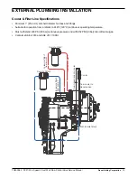
Page 17: ...tings Suitable for operation from ambient to 248 F 120 C continuous operating temperature Must withstand 435 PSI 30 bar continuous pressure and with 652 PSI 40 bar intermittent surges Conforms SAE J1019 and SAE J517 100RI to remote filter 1 from pump 1 from remote filter 1 from remote filter 2 from transmission to cooler from cooler to transmission Cooler Remote Filter 1 to remote filter 2 from pu...

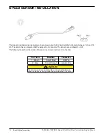
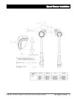
Page 18: ...en 7 mA and 14 mA The sensor has an integrated AMP superseal 2 pin connector The two pins are numbered 1 and 2 The following table shows the relation between wire color pin number and connection Pin Color Function Connection 1 Brown Current Input Hot Wire 2 Blue Current Output Ground Wire The sensor wires have a polarity Be sure to correctly observe sensor polarities as wrong connections will deac...

Page 19: ...TSM 0064 TE27 32 4 Speed LD with Full Flow Control Valve Service Manual Dana Holding Corporation 16 Speed Sensor Installation Speed Sensor Installation ...

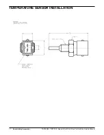
Page 20: ...17 Dana Holding Corporation TSM 0064 TE27 32 4 Speed LD with Full Flow Control Valve Service Manual TEMPERATURE SENSOR INSTALLATION ...

Reviews: