


26
Advanced Operation
Feeding a video device with SMPTE bars and then
feeding the signal into a vectorscope and terminated
monitor allows for checking the chroma phase. Select the
75 percent bars gain button on the vectorscope, and turn
the phase knob to line up with the reference flag to 0
degrees. The points of the displayed pattern land inside
the squares for each color vector.
6.2 Resetting VIP to Factory Defaults
Certain issues require the VIP to be reset to its factory
defaults. Confirm the following before resetting
the VIP.
1.
No video output is visible on the display.
2.
Bypass the VIP to verify the VMax
TM
signal
works correctly.
3.
Ensure functionality of inputs via VIP
web monitoring.
Note:
If web monitoring is unavailable, do not reset
the VIP.
4.
Verify the system configuration and display are
working correctly by switching to the backup
system (if available).
Locate the backup configuration settings before reset, as the factory reset process will remove
any configuration on the VIP. In the absence of a functional configuration backup, the
configuration must be re-entered manually. Typical locations include Venus 7000 scripts or
command frames, as well as .VLC files.
Note:
Save the configuration as a new file.
1.
Open the VLink Debugger. The VLink Debugger can be found under the Start menu in
Programs > Venus 7000 > Venus 7000 Tools > V7 VLink Debug
. For more information
on the V7 VLink Debugger, refer to
DMP-7000 Installation and Setup
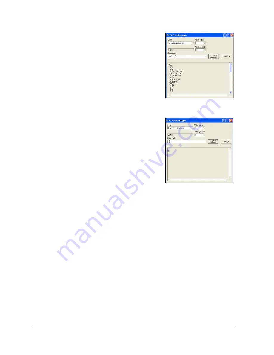
2.
In the VLink Debugger Command box, type “XRD,” which deletes all configuration
settings and restarts the VIP. Refer to
3.
Wait one minute to allow the VIP to reboot, then type “XR” and click
Send Command
.
Allow a minute for the VIP to reboot, then click
[Enter]
while the cursor is in the VLink
Debugger Command box. When 1> appears in the readout window, the VIP has
completed the reboot. Refer to
Figure 18: Entering “XRD” Command
Figure 19: Completed Reboot