background image

Specifications & Schematics

31

Specifications & Schematics

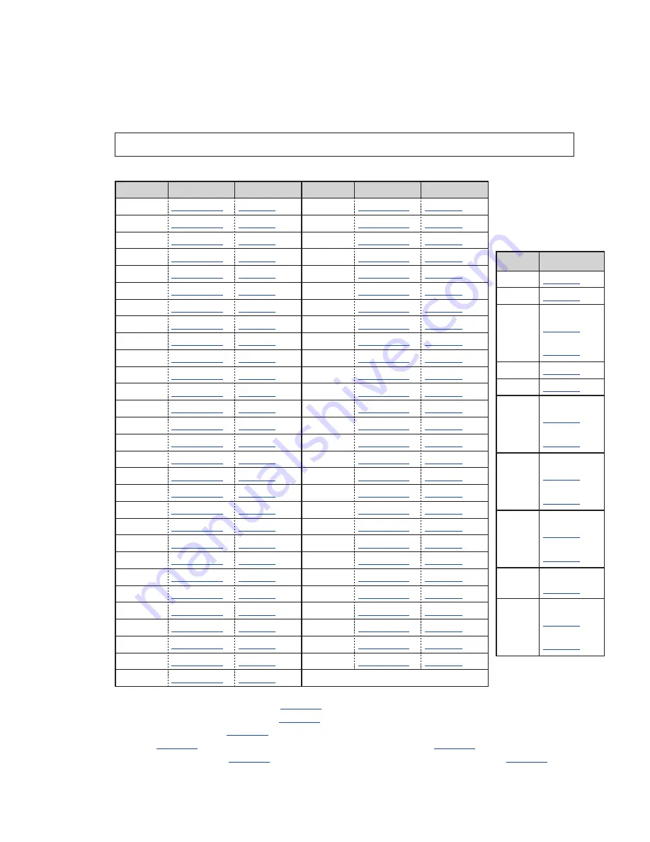
Click the links below to view scoreboard product specification sheets and schematic 

drawings. Product-specific installation and component location drawings are included 

with each spec sheet or linked below. 

Note: 

Refer to 

Figure 1

 to determine a display's model number. 

Single-Section Models

Model

Spec Sheet Schematic Model

Spec Sheet Schematic

BA-618

DD2118104

1194169

MS-2006

DD2240343

3302813

**

BA-624

DD2118116

1194169

MS-2012

DD2167432

3312544

*

BA-2005

DD2118134

1066858

MS-2024

DD1745306

3312544

*

BA-2010

DD2121807

1194169

MS-2025

DD1745311

1194169

BA-2014

DD2118163

1066858

MS-2028

DD3645470

3312544

BA-2017

DD2118169

1194169

MS-2029

DD3645488

3312544

BA-2019

DD2118182

1066858

MS-2030

DD4042205

3312544

BA-2022

DD2118191

3312544

*

MS-2032

DD4046839

3312544

BA-2023

DD3023964

1194169

MS-2126

DD3312907

1194169

BA-2030

DD2467046

1066858

MS-3918

DD1734766

1194169

BA-2031

DD3023984

1194169

RO-2010

DD1756861

1194169

BA-2032

DD3193775

1194169

RO-2011

DD1756894

1194169

BA-2033

DD3504339

1194169

RO-2019

DD3634134

1194169

BA-2034

DD3504365

1194169

SO-918

DD2167442

1194169

BA-2035

DD3504441

1194169

SO-2008

DD2167448

3302813

***

BA-2515

DD1734711

1194169

SO-2013

DD2167468

3312544

*

BA-2518

DD1739303

1194169

SO-2918

DD1734747

1194169

BA-2618

DD1734727

1194169

TI-218

DD1757007

1194169

BA-2715

DD1734734

1194169

TI-2003

DD1757027

1194169

BA-2718

DD1734740

1194169

TI-2010

DD1757109

1194169

CR-2002

DD1756601

1194169

TI-2012

DD1757303

1194169

CR-2003

DD2167525

3312544

*

TI-2015

DD1757334

1194169

FB-824

DD2167261

1194169

TI-2019

DD1757391

1194169

FB-4005

DD1734755

1194169

TI-2024

DD2191318

1194169

****

FB-2030

DD2190567

3312544

*

TI-2032

DD1893381

1194169

MS-915

DD1756705

1194169

TI-2033

DD3017701

3034919

MS-918

DD2167408

3302813

**

TI-2034

DD3632181

1194169

MS-2002

DD2167412

3312544

*

TI-2035

DD3632311

1194169

MS-2004

DD2167420

3312544

*

    * If built before May 2016, see 

1202017

  ** If built before May 2016, see 

3002321

 *** If white digits, see 

3312544

. If red/amber digits 

and

 built before May 2016,  

       see 

3002321

; if white digits 

and

 built before May 2016, see 

1202017

**** If white digits, see 

3302813

. If white digits 

and

 built before May 2016, see 

3002321

The following models 

may have different 

component locations 

than shown in the 

spec sheets: 

Model

Drawing

BA-2005

1066866

BA-2019

1066797

BA-2026

Red/Amber: 

1049222

White: 

3025697

BA-2125

1151033

BA-2127

1152718

MS-2002

Red/Amber:

1066547

White:

3025614

MS-2006

Red/Amber:

1086360

White:

3025634

MS-2028

Red/Amber:

3935842

White:

3945258

MS-2029 R/A/W:

3719486

MS-2030

Red/Amber:

3979226

White:

3979227

Summary of Contents for BA-1518

Page 1: ...3004 AR 2424 CH 3006 Tennis Models TN 2603 TN 2651 TN 2604 TN 2652 TN 2605 TN 2653 TN 2606 TN 2654 TN 2607 TN 2655 TN 2609 TN 2656 TN 2650 TN 2657 Pari Mutuel Models PM 2100 PM 2108 PM 2101 PM 2109 PM 2102 PM 2110 PM 2103 PM 2111 PM 2104 PM 2112 PM 2105 PM 2113 PM 2106 PM 2114 PM 2107 Modular Football Models FB 2500 Series FB 2600 Series Hybrid Football Models FB 2700 Series Single Section Models ...

Page 2: ...No part of this book covered by the copyrights hereon may be reproduced or copied in any form or by any means graphic electronic or mechanical including photocopying taping or information storage and retrieval systems without written permission of the publisher Daktronics trademarks are property of Daktronics Inc All other trademarks are property of their respective companies ...

Page 3: ...ting the Driver Address 10 Single Section Models 10 Tennis Models 10 Modular Football Models 11 Hybrid Football Models 11 Multi Section Models 11 Pari Mutuel Models 12 Motorsports Models 12 Power Supplies 13 Replacing a 300 W Power Supply 13 Replacing a 1000 W Power Supply Prior to May 2016 13 Radio Connections 14 Radio Interference 14 All Sport Radio Receiver 15 RC 100 Base Station 15 RC 200 Base...

Page 4: ...tripping 26 Power Supplies 26 Replacing a Power Supply 26 Display Maintenance 26 Replacement Parts 27 4 Daktronics Exchange and Repair Return Programs 28 Exchange Program 28 Repair Return Program 29 Daktronics Warranty Limitation of Liability 29 A Specifications Schematics 31 B Reference Drawings 37 C Daktronics Warranty Limitation of Liability 39 ...

Page 5: ... Power specifications as well as serial and model number information can be found on an ID label affixed to the display similar to the one shown in Figure 1 DAKTRONICS 201 DAKTRONICS DR BROOKINGS SD PHONE 800 325 8766 SUITABLE FOR SERVICING ONLY WHEN DE ENERGIZED PUET FAIRE L OBJET D UN ENTRETIEN UNIQUEMENT S IL EST HORS TENSION CONFORMS TO UL STD 48 CERTIFIED TO CSA STD C22 2 NO 207 17800 0A 1647...

Page 6: ...quantities Project specific information takes precedence over any other general information found in this manual Ensure all applicable material has been gathered before servicing Contact a Daktronics sales coordinator or project manager Daktronics Nomenclature Most display components have a white label that lists the part number Figure 3 Part numbers will also appear on certain drawings If a compo...

Page 7: ...onsole if necessary Display digits do not light but console works No wired signal from control console Check that the display is receiving 100 240 VAC power Check that the red DS5 LED on the driver lights up when sending commands from the console See LED Drivers p 8 No radio signal from control console Verify that both the console and display antennas are securely tightened and in a vertical posit...

Page 8: ...onnection Verify the connector on the back of the digit circuit board is secure Bad digit or driver Exchange the digit or driver with a working one of the same part to verify the problem Replace if necessary See Replacing Digits p 6 Replacing Digit Segments p 7 Replacing Colons Decimals Indicators p 7 or LED Drivers p 8 Display works but some digits do not light Bad digit or driver see solution ab...

Page 9: ...All internal electronic components are reached by opening a digit panel or an access door Look for labels similar to those shown in Figure 4 to access primary display components Note that the same labels are on both front and rear access panels SERVICING DISCONNECT POWER BEFORE LOCATED BEHIND THIS PANEL CONTROL UNIT AND FUSES ARE CAUTION LL 1065 REV 2 BEHIND THIS PANEL DRIVER IS LOCATED PRIMARY TH...

Page 10: ...d to a black polycarbonate tray and encased in protective gel This weather sealed digit tray is mounted to the back of a digit panel as shown in Figure 6 Multiple digits may be secured to a single face panel Do not attempt to remove individual LEDs in the case of a malfunctioning LED or digit segment replace the entire digit To replace a digit 1 Open the digit panel as described in Component Locat...

Page 11: ...nd it will attach in one way only Do not force the connection 6 Close and secure the digit panel and then power up and test the display to verify the issue has been resolved Some LED digit segments are connected to a breakout board Figure 8 If all the segments of an entire digit do not work it may be necessary to replace the breakout board instead Breakout boards are replaced in the same manner as...

Page 12: ...071833 LED drivers perform the task of switching digits on and off within the display LED drivers are located inside a driver enclosure Refer to Figure 9 to view the location and components of a driver enclosure For detailed descriptions and pin outs of the driver jacks refer to DWG 3071833 H L 0 1 2 3 4 5 6 7 8 9 A B C D E F 0 1 2 3 4 5 6 7 8 9 A B C D E F DAKTRONICS 201 DAKTRONICS DR BROOKINGS S...

Page 13: ...m with the secondary driver s or the power signal connection from the other driver s Refer to the appropriate scoreboard installation manual or the schematics in Appendix A for more information Replacing a Driver 1 Open the digit panel or display face panel nearest the driver as described in Component Locations Access p 5 2 Remove the metal cover of the driver enclosure by lifting it up then back ...

Page 14: ... BA 2017 BA 2515 BA 2518 BA 2618 A1 61 BA 2715 BA 2718 A1 62 BA 2005 BA 2014 BA 2019 BA 2030 A1 72 A2 70 A3 71 BA 2022 A1 70 A2 64 BA 2023 BA 2031 BA 2033 BA 2034 BA 2035 A1 3 BA 2032 A1 60 CR 2002 A1 12 CR 2003 A1 12 A2 13 FB 824 FB 4005 MS 915 MS 918 MS 2002 MS 2006 MS 2025 MS 3918 SO 918 SO 2918 A1 A2 11 Additional driver s only for models with white digits Prior to October 2018 A1 64 A2 70 Ten...

Page 15: ...A1 72 A2 70 A3 71 A4 1 BA 2028 BA 2029 A1 A7 72 A2 A3 70 A3 A4 A5 71 A4 A6 FB 3010 A1 10 A2 1 MS 2009 A1 72 A2 A4 71 A3 73 MS 2027 A1 15 A2 71 A3 72 A4 73 Additional driver s only for models with white digits The BA 2029 requires a seventh driver with white digits The SO 2021 and SO 2023 require a fourth driver with white digits Model Driver Address FB 2018 FB 2019 FB 2020 FB 2021 FB 2022 FB 2023 ...

Page 16: ...4 A1 11 AR 2406 A1 11 A2 12 AR 2407 A2 12 Model Driver Address PM 2108 A1 23 A2 24 A3 25 PM 2109 A1 A2 26 A3 27 PM 2110 A1 21 Pool 230 G PM 2111 1 5 A1 70 A2 71 A3 72 PM 2111 6 10 A4 72 A5 73 A6 74 PM 2112 A1 A3 26 A2 A4 27 PM 2113 A1 A3 26 A2 A4 27 Display Section Driver Address Time Lap Counter Position 1 3 Position 1 5 A1 11 Position 6 10 A1 12 Position 11 15 A1 13 Position 16 20 A1 14 Model Dr...

Page 17: ...losure securely close the access panel and then power up and test the display to verify the issue has been resolved Replacing a 1000 W Power Supply Prior to May 2016 Reference Drawings Enclosure 1000W Power Supply DWG 274431 1 Open the digit panel or display access panel nearest the power supply as described in Component Locations Access p 5 2 Loosen the screws to remove metal cover from the power...

Page 18: ... these settings do not appear the radio receiver may need to be repaired replaced To make sure the channel and broadcast settings of the receiver in the display match those set in the console scoring app refer to the appropriate control console manual Radio Interference If it has been determined that a nearby display s radio signal is interfering the settings of the radio receiver or wireless base...

Page 19: ...igure 12 Note While it is necessary for the display to be powered on to check the indicators always disconnect power before servicing 2 Remove the four screws in each corner using a 2 Philips screwdriver and lift off the cover 3 Use a small flathead screwdriver to set the CHAN and BCAST switches to a new channel and broadcast group 1 8 as needed The FUNC switch will typically be set to 2 for most ...

Page 20: ...ponents will have attached part number labels Description Part Number Digit 10 7 seg outdoor LED red 0A 1192 5120 Digit 15 7 seg outdoor LED red 0A 1192 5130 Digit 18 7 seg outdoor LED red 0A 1192 5140 Digit segment 24 outdoor LED red vertical 0A 1192 5150 Digit segment 24 outdoor LED red horizontal 0A 1192 5151 Digit segment 30 outdoor LED red vertical 0A 1192 5160 Digit segment 30 outdoor LED re...

Page 21: ...t segment 24 outdoor LED white horizontal 0A 1192 5451 Digit segment 30 outdoor LED white vertical 0A 1192 5460 Digit segment 30 outdoor LED white horizontal 0A 1192 5461 Digit segment 36 outdoor LED white vertical 0A 1192 5470 Digit segment 36 outdoor LED white horizontal 0A 1192 5471 Digit segment 48 outdoor LED white vertical 0A 1192 5480 Digit segment 48 outdoor LED white horizontal 0A 1192 54...

Page 22: ...A 1000W power supply F 1058 Circuit Breaker 15A 120 240 VAC power panel S 1035 RFI Filter power panel Z 1007 Use these digit segments to replace individual pieces of small possession indicators Use these digit segments to replace individual pieces of large possession indicators Use for 36 and 48 digits built after May 2016 Use for 36 and 48 digits built prior to May 2016 The entire digit panel mus...

Page 23: ...ber or white LEDs Refer to the table below for additional message center specifications DAKTRONICS HAWKS BEARS TNMC Electronic Caption DOWN TOGO BALLON QTR Figure 15 Football Scoreboard with TNMCs and Electronic Captions Matrix Size Weight of 8x8 Modules Active Display Area Pixel Spacing 8x32 40 lb 18 kg 4 10 6 x 42 5 269 mm x 1080 mm 34 mm 1 3 8x48 60 lb 27 kg 6 10 6 x 63 8 269 mm x 1621 mm 8x64 ...

Page 24: ...r is garbled Replace the first module See Modules p 25 Replace the display driver See Display Drivers p 23 A group of modules which shares the same power supply assembly fails to work Replace the power supply assembly See Power Supplies p 26 Entire display fails to work Check for proper line voltage into the power termination panel Check replace the ribbon cable from the display driver to the modu...

Page 25: ...e same harness and J42 P43 connections as signal power is routed to the display driver where it then travels to the power supply assembly 2 From the power supply power is relayed to the first module and then from module to module 3 The modules and display driver draw their power directly from the power supply assemblies 3 12 5 VDC The power supply voltage is set by a resistor loaded on the module ...

Page 26: ...5635 Display Driver Ground Terminal Block Power Supply All LED Colors Power Supply White LED Only Figure 18 8x48 46mm Display with Modules Removed Note White 46mm TNMCs built after May 2017 feature power supply enclosures with covers that must be removed to access the power supply Daktronics outdoor LED scoreboards are typically front accessible but some models may be ordered with rear service acc...

Page 27: ...nal power supplies are noted in the appropriate component location drawing Primary Power Supply Display Driver Figure 20 Display Cabinet Rear Access Panels Display Drivers Reference Drawings Address Table Driver MCAST G2 TNMC Switch DWG 328274 Specifications Driver MCAST 4 Col DWG 793970 Power and Address Details Outdoor Tennis Scoreboards DWG 1202417 The display driver detailed in DWG 793970 in A...

Page 28: ...r before servicing LED Function Color Illumination Summary DS1 Signal TX Green Steady on or blinking when the driver is transmitting and off when there is no signal DS2 Signal RX Red Steady on or blinking when the driver is receiving signal and off when there is no signal DS3 Power Green Steady on to indicate the driver has power DS4 Status Amber Blinking to indicate driver is running steady on or...

Page 29: ...fy the issue has been resolved To replace a module from the rear 1 Follow the steps as described in Rear Access p 23 2 Use a 1 8 hex wrench to loosen the latch fastener assembly Figure 22 Turn each fastener 1 4 turn Do not over turn the fastener 3 While holding onto the module push it out and turn it in such a manner generally a sideways diagonal turn that it can be pulled back through the frame o...

Page 30: ... 23 2 Disconnect all wires connected to the power supply 3 Remove the hardware holding the power supply in place and slide it out of the display cabinet 4 Fasten the new power supply in place and reconnect all wires 5 Power up and test the scoreboard display to verify the issue has been resolved Display Maintenance Complete a yearly inspection to maintain safe and dependable display operation This...

Page 31: ...Amber 0A 1541 5009 Module 8X8 46 White 0A 1541 5006 Driver MCAST 4 Column 0P 1388 0201 Power Supply 9V 85 264V AC 150W white 46mm built after May 2017 A 2259 Power Supply 3 6 5V 90 264V AC 135W all 34mm LED colors amber 46mm red 46mm A 2307 Power Supply 8 5 12 5V 90 264V AC 150W white 46mm A 2481 Fan 12VDC white 46mm built after May 2017 B 1103 Electrical contact lubricant CaiLube CH 1019 Cable 20...

Page 32: ..._____ To participate in the Exchange Program follow these steps 1 Call Daktronics Customer Service Market Description Customer Service Number Schools including community junior colleges religious organizations municipal clubs and community centers 877 605 1115 Fax 605 697 4444 Universities and professional sporting events live events for auditoriums and arenas 866 343 6018 Fax 605 697 4444 2 When ...

Page 33: ...amage during shipment Electronic components such as printed circuit boards should be placed in an antistatic bag before boxing Daktronics does not recommend using packing peanuts when shipping 4 Enclose name address phone number the case number a clear description of symptoms 5 Ship to Daktronics Customer Service Case 201 Daktronics Drive Dock E Brookings SD 57006 Daktronics Warranty Limitation of...

Page 34: ...This page intentionally left blank ...

Page 35: ...2515 DD1734711 1194169 SO 2013 DD2167468 3312544 BA 2518 DD1739303 1194169 SO 2918 DD1734747 1194169 BA 2618 DD1734727 1194169 TI 218 DD1757007 1194169 BA 2715 DD1734734 1194169 TI 2003 DD1757027 1194169 BA 2718 DD1734740 1194169 TI 2010 DD1757109 1194169 CR 2002 DD1756601 1194169 TI 2012 DD1757303 1194169 CR 2003 DD2167525 3312544 TI 2015 DD1757334 1194169 FB 824 DD2167261 1194169 TI 2019 DD17573...

Page 36: ...e May 2016 see 3002321 If built before May 2016 see 3001199 Modular Football Models Click the linked drawing numbers below to view the component location and schematic drawings for a specific scoreboard model or combination of models Clock Sections Model Component Location Schematic FB 2500 1086738 1194169 FB 2501 1111383 1194169 FB 2502 Red Amber 1101698 White 3356744 3302813 FB 2503 3260181 1194...

Page 37: ...ite 4143382 3312544 FB 2566 1097707 3312544 Guest Score Sections Model Component Location Schematic FB 2570 w 2571 1068546 3311698 FB 2572 w 2573 1086755 3311698 FB 2574 w 2575 Red Amber 1104417 White 3364955 3311698 FB 2576 w 2577 3085582 3311698 FB 2578 w 2579 1101718 3311698 FB 2580 To Be Determined 3311698 FB 2582 w 2583 1092550 3311698 FB 2584 w 2585 3096211 3311698 FB 2586 w 2587 3672414 331...

Page 38: ... FB 2622 1103590 B 3312544 FB 2623 1103617 B 3312544 FB 2624 1121548 B 3312544 FB 2625 1121550 B 3312544 FB 2626 Red Amber 1158571 White 3381824 B 3312544 FB 2627 Red Amber 1158572 White 3381834 B 3312544 FB 2630 w 2628 Red Amber 1092493 White 3407090 B 3311698 FB 2629 w 2631 Red Amber 1092527 White 3407091 B 3311698 FB 2632 3044761 B 3312544 FB 2633 3044762 B 3312544 FB 2656 To Be Determined B 33...

Page 39: ...rmined 3312544 Team Name Message Centers Pixel Spacing Schematic Red Amber White 34 mm 783938 906385 46 mm 923941 3638033 34mm 16x60 1092559 If built before May 2017 see 1036125 Tennis Models Model Spec Sheet Schematic Model Spec Sheet Schematic TN 2603 DD2731384 3302813 TN 2651 DD2731389 1076663 1076660 TN 2604 DD2731386 3302813 TN 2652 DD2731390 1093329 1093330 TN 2605 DD2731387 3302813 TN 2653 ...

Page 40: ...910645 3002272 DR 3682 DD2910658 3312544 AR 2426 DD2910647 3002272 DR 3683 AR 2427 DD2910648 1194169 DR 4882 DD2910660 3302813 AR 2428 DD2910650 1194169 DR 4883 If built before May 2016 see 1202017 If built before May 2016 see 3002321 Pari Mutuel Displays Model Spec Sheet Schematic Model Spec Sheet Schematic PM 2100 DD2910222 1143319 PM 2108 DD2910230 1143319 PM 2101 DD2910223 1194169 PM 2109 DD29...

Page 41: ...wer Supply 274431 Address Table Driver MCAST G2 TNMC Switch 328274 Specifications Driver MCAST 4 Col 793970 Component Loc 34mm Red Amb Wht LED TNMC G4 975100 Component Loc 46mm Red Amb Wht LED TNMC G4 975635 Wiring Detail FB 2534 or 2541 for TNMC Type Options 1092840 Address Table Rotary Switches H and L 1198765 Power and Address Details Outdoor Tennis Scoreboards 1202417 Specifications Gyrus LED ...

Page 42: ...This page intentionally left blank ...

Page 43: ...Daktronics Warranty Limitation of Liability 39 C Daktronics Warranty Limitation of Liability This section includes the Daktronics Warranty Limitation of Liability statement SL 02374 ...

Page 44: ...This page intentionally left blank ...

Page 45: ...ty per Incoterms 2020 otherwise End User shall pay transportation charges to return the Equipment back to the End User and such Equipment shall be shipped Ex Works Daktronics designated facility per Incoterms 2020 All returns must be pre approved by Daktronics before shipment Daktronics shall not be obligated to pay freight for any unapproved return End User shall pay any upgraded or expedited tra...

Page 46: ... Daktronics or M paint or refinishing the Equipment or furnishing material for this purpose 3 Limitation of Liability A Daktronics shall be under no obligation to furnish continued service under this Warranty if alterations are made to the Equipment without the prior written approval of Daktronics B It is specifically agreed that the price of the Equipment is based upon the following limitation of...

Page 47: ...ration of this warranty Alternatively an Extended Service Agreement may be purchased in conjunction with this Warranty for extended additional services For further information contact Daktronics Customer Service at 1 800 DAKTRONics 1 800 325 8766 Additional Terms applicable to sales outside of the United States The following additional terms apply only where the installation site of the Equipment ...

Page 48: ...This page intentionally left blank ...

Reviews: