31
WARNING
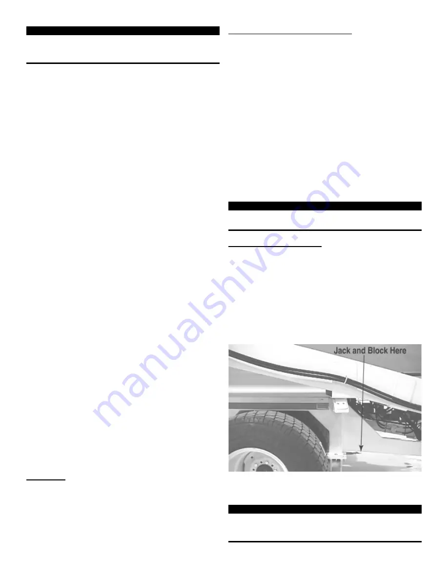
Do not perform maintenance of any kind below the
Turf Tender unless it is properly secured and
stabilized.
4. Remove the eight walking beam axle mounting bolts and
nuts (four at the front and four at the rear). Roll axle
assembly out to the rear.
5. Stand the axle assembly on end and remove the wheel
bolts; then remove the wheels.
6. For each wheel bearing, remove the grease cap.
7. Bend the cotter key straight and remove; then remove the
spindle nut and washer.
8. Remove the hub from the spindle being careful not to
allow the outer bearing to fall out. The inner bearing will
be retained by the seal on the back side of the hub assembly.
NOTE: It is important to protect the wheel bearing
bores (inside portion of the hub) from metallic chips
and contamination. Ensure the wheel bearing
cavities are clean and free of contamination before
installing the bearings and seal.
9. Using a suitable solvent, wash all grease and oil from the
bearings. Dry the bearing with a clean, lint-free cloth;
then thoroughly inspect each bearing. If any pitting,
spalling, or corrosion is present, the bearing must be
replaced.
NOTE: Bearings must always be replaced in sets of
inner and outer bearings.
10. Inspect the seal to assure that it is not nicked or torn and
is still capable of sealing the bearing cavity.
11. Pack the bearings with a Lithium complex NLGI No. 2
grease.
12. Assemble the hub (seal, bearings, spindle washer, and
spindle nut) back on the spindle being careful to not spill
grease on the outside of the spindle (backside) where it
could drop onto the brakes.
13. Rotate the hub assembly slowly while tightening the
spindle nut to approximately 50 ft-lb (7 kg-m); then loosen
the spindle nut to remove the torque. Without rotating the
hub, finger tighten the spindle nut until just snug. Back
the spindle nut out slightly until the first castellation (slot)
lines up with the cotter key hole and insert the cotter key.
Spread the legs of the cotter key.
NOTE: The nut should move freely with the only
restraint being the cotter key.
14. Install the spindle cap.
15. Install the wheels; then install the axle assembly. Refer to
the “Changing an Inside Tire” section for the procedure
and proper torque specifications.
ELECTRIC BRAKES
Features
Electrically actuated brakes have several advantages over
other brake actuation systems.
1. They can be manually adjusted to provide the correct
braking capability for varying terrain and load conditions.
2. They can be modulated to provide more or less braking
force, thus easing the brake load on the towing vehicle.
3. They can provide braking independent of the tractor.
Testing the Brake Controller
To perform a quick and easy test on the brake control, use
a 12-volt test light (not a voltmeter) and the following procedure:
1. Connect the ground clip from the test light to a solid
ground (WHITE wire) and pierce the brake wire (BLUE
wire) with the point of the test light.
2. Activate the brake switch and hold. The test light should
get steadily brighter in intensity. Release the brake switch
and the test light should go out.
This test allows you to quickly see if the brake controller is
functioning properly. If the controller tests good with a test
light, but will not work properly with a Turf Tender connected,
check for a poor connection or broken wire.
NOTE: Minimum vehicle stopping distances are
achieved when the wheels approach lockup. Brake
lockup should be avoided as it results in poor vehicle
stability and control. Depending upon load, driving
surface, wheels and tires, not all brakes are capable
of wheel lockup under all conditions.
WARNING
Do not adjust the controller outside the parameters
outlined in these instructions.
General Maintenance
BRAKE ADJUSTMENT
Brakes should be adjusted: after the first 10 hours of
operation when the brake shoes and drums have “seated,” at
300 hour intervals thereafter, and as use and performance
requires. To adjust the brakes, use the following procedure:
1. Empty all material from the hopper; then chock the
wheel(s) on the opposite side of the Turf Tender.
2. With the Turf Tender hooked to a tractor that has the parking
brake set, jack up the frame directly in front of the axle
mount. Check that the wheel and drum rotates freely.
3. Using jack stands, support the frame so it is safe to work
beneath. Under no conditions should cement blocks
(cinder blocks) or unstable piles of wood blocks be used.
WARNING
Do not perform maintenance of any kind below the
Turf Tender unless it is properly secured and
stabilized.
MAINTENANCE


