Unit Operation – General
Mark IV/AC-Control Units
Note:
At start-up of unit, ensure that temperature, flow rate
and voltage are within specified limits required for
proper unit operation. Each unit has its own control
or remote control, utilizing an internal thermostat (unit
mounted) and touch-pad selector switch or a wall
mounted thermostat (remote control units).
Each unit has a Mark IV/AC version printed circuit board.
Its control is available in unit mounted or remote wall
thermostat. The Mark IV/AC controller has a 14-pin low
voltage terminal strip for a hardwired interface for all
the necessary field connections interfacing to external
equipment (see Table 8). The low voltage output from
the low voltage terminal strip is always 24 volts AC.
Terminals F and V on the low voltage terminal strip
supply 24 volts DC-power.
Table 8: 14-Position Terminal Strip
Pin
Designation
Description
1
C
Transformer ground (0vac)
2
R
Transformer supply (24vac)
3
V
– DC power connection
4
P
Pump request output
5
A
Alarm fault output
6
U
Unoccupied input
7
L
Load shed input
8
E
Remote shutdown input
9
F
+DC power connection
10
Y1
Occupied cooling mode input
11
W1
Occupied heating mode input
12
G
Fan only input
13
W2
Unoccupied heating mode input
14
O
Tenant override input
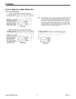
The 24 volt low voltage terminal strip is set up so R-G
or F-G energizes the fan, R-Y1 or F-Y1 energizes
the compressor for cooling operation, R-W1 or F-W1
energizes the compressor and reversing valve for
heating operation. The reversing valve is energized in
the heating mode. The circuit board has a fan interlock
circuit to energize the fan whenever the compressor’s on
if the thermostat logic fails to do so.
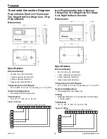
Remember the output to the wall stat can be AC current
or DC current. Terminal (R) on the wall stat can be
connected to terminal (R) on the PC board for AC voltage
or to terminal (F) on the PC board for DC voltage.
AC current
DC current
R to G = fan only
F to G = fan only
R to Y1 = cooling
F to Y1 = cooling
R to W1 = heat F to W1 = heat
Continuous Fan:
Units are factory wired for continuous
operation. When power is applied and the start switch is
depressed, the fan will run.
Cooling or Heating – Auto Operation:
Rotate the
thermostat knob to either warmer or cooler. Select fan
speed. Depress the start button. Unit will start within 0 to
32 seconds.
Lockout Circuit:
Each unit has its own lockout circuit
to lock out compressor operation when an abnormal
condition should appear. During unit operation, the
compressor will be automatically turned off due to one
of the two safety openings. High pressure is set at 600
psi (4136 kPa) and low temperature switch is set at 28˚F
(-2˚C). Condensate overflow and brownout protection
are also included.
Remote Reset of Automatic Lockouts:
The Remote
Reset feature provides the means to remotely reset
automatic lockouts generated by high-pressure and/or
low-temperature (in heating) faults. When the Mark IV
board is in automatic lockout due to one of these faults,
and the cause of the fault condition has been alleviated,
energizing the O-terminal for 10 seconds or more will
force the Mark IV board to clear the lockout. A unit power
cycle can also be used to clear an automatic lockout if
the conditions causing the fault have been alleviated.
Fault Retry To Minimize Nuisance Trips:
The Fault
Retry feature helps to minimize nuisance trips of
automatic lockouts caused by high-pressure and/or low-
temperature (in heating) faults. This feature clears faults
the first two times they occur within a 24-hour period and
triggers an automatic lockout on the 3rd fault. The retry
count is reset to zero every 24 hours.
Cooling or Heating – Manual Operation:
Rotate the
thermostat knob to either warmer or cooler. Select fan
speed, depress the heat or cool button, and unit will start
within 0 to 32 seconds.
The Mark IV/AC-circuit board system has built-in
features such as random start, compressor time delay,
night setback, load shed, shutdown, condensate
overflow protection, defrost cycle, brownout, and LED/
fault outputs. Table 9 shows the LED and fault output
sequences. The 24 volt low voltage terminal strip is set
so R-G energizes the fan. R-W1 energizes the fan and
compressor and reversing valve for heating operation.
The reversing valve is set up to be energized in the
heating mode. The circuit board has a fan interlock circuit
to energize the fan whenever the compressor is on.
www.DaikinApplied.com 15
IM 447-11

