The Mark IV/AC control board has a lockout circuit to
stop compressor operation if any one of its safeties
opens (high pressure or low temperature). If the low
temperature thermostat opens, the unit will go into the
cooling mode for 60 seconds to defrost any slush in the
water-to-refrigerant heat exchanger. After 60 seconds,
the compressor is locked out. If the condensate sensor
detects a filled drain pan, the compressor operation will
be suspended only in the cooling mode.
The unit is reset by opening and closing the disconnect
switch on the main power supply to the unit in the event the
unit compressor operation has been suspended due to low
temperature (freezestat) switch, or high pressure switch.
The Mark IV/AC control circuit has a fault output signal to an
LED on a wall thermostat. Table 9 shows in which function
the fault output is “on” (sending a signal to the LED).
Table 9: Mark IV/AC LED & fault outputs
Indication
LED
Fault
Yellow
Green
Red
Output
Normal Mode
Off
On
Off
Off
Pressure Fault
Off
On
Flash
On
Low Temperature Fault*
Flash
Off
Off
On
Condensate Overflow**
On
Dim
Off
On
Brownout
Off
Flash
Off
On
Load Shed
Off
Off
On
Off
Unoccupied Mode
On
On
Off
Off
Unit Shutdown
Off
Flash
Off
On
* Only in the heating mode ** Only in the cooling mode
Motorized Valve & Relay for Unit Sizes
009 to 019
Wired as shown below the motorized valve will open
on a call for compressor operation. Valves for unit sizes
009 to 019 are 1/2" power-open spring-return. Other
thermostat combinations may be used. Valve and
auxiliary relay are purchased separately.
Note:
The wiring shown below can only be used when
the “P” terminal is not being used as a pump re
-
start signal to other equipment. If the “P” terminal
must be used as a pump restart signal to other
equipment, then wire the auxiliary relay’s yellow
wire to “Y1”, white wire to “W1”, and orange wire
to “C”, then the valve will open on a call for oc
-
cupied heating or cooling from the thermostat.
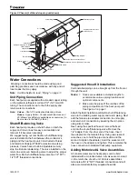
Figure 10: Normally Closed, Power Open Motorized Valve
Wiring
Actuator & Valve
Assembly
Anti-short Bushing
Connector
Conduit
Pin(s), female
connect to terminal H8
Connector
Anti-short
Bushing
Notes:
1. Connectors on valve must be cut off and
stripped back and the wires twisted to make
connections to the H8 (IV/PR) terminals on
the Mark IV controller.
2. All plumbing connections are made the
same, whether or not the unit has valve
packages. Plumbing connections must
conform with local piping and building codes.
The ability to remove the unit in order to per
-
form repairs is imperative.
Figure 11: Motorized Valve Kit
Water Flow
Use Upper
Knockout
Conduit, Fitting
Bushing
Conduit
Elbow
Water Tube Extension
Conduit, Fitting Bushing
Motorized
Valve
WH
YE
OR
GN7
BL6
BL6
BL9
BL8
BL9
BL8
6 3 1
GN7
PC Board
Terminal Strip
Motorized Valve
Control Relay
Receptical
Water Flow
Use Upper
Knockout
Conduit, Fitting
Bushing
Conduit
Elbow
Water Tube Extension
Conduit, Fitting Bushing
Motorized
Valve
WH
YE
OR
GN7
BL6
BL6
BL9
BL8
BL9
BL8
6 3 1
GN7
PC Board
Terminal Strip
Motorized Valve
Control Relay
Receptical
Notes:
1. Use soft solder process on water tubing outside of chassis.
2. Route wires along with power leads.
3. Left hand installation shown - right hand installation is “mirror” opposite.
4. Motorized valve (511) to be parallel to the end panel.
5. Copper to be washed prior to soldering.
6. Route conduit so it does not interfere with manual operation of
motorized valve.
IM 447-11
16 www.DaikinApplied.com


