t
ypiCal
W
iring
d
iagraMs
Console WSHP Size 009–019, All Voltages, 60Hz / Single Phase, Mark IV Board with
Auto Changeover (ACO)
- Plug Connection
TB - Terminal Block
ACO - Automatic Changeover
MCO - Manual Changeover
BR - Boilerless Relay
HR - Heater Relay
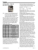
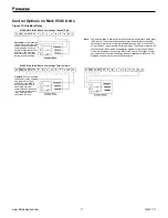
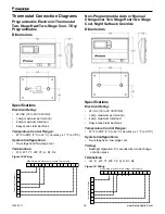
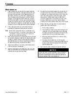
Component Layout
1.
Tap-Touch Switch
2. Thermostat
3.
Terminal Block
4.
PC Board
5. Transformer
6.
Boilerless Relay
7.
Shutdown Relay
8.
Auxiliary Relay
9.
Heater Relay
10. Water Reg Valve Relay
11. Low Limit Thermostat
12. Night Setback Thermostat
13. Override Switch
14. Terminal Board 1
15. Terminal Board 2
16. Stop/Start Switch
17. Standby Electric Heat Switch
Notes:
1.
Terminal block on PC board provides 24
VAC at terminals C and R. All other
terminals are 24 VDC output.
2.
All temperature and pressure switches
are normally closed.
3.
Component layout is typical, some
components shown may not be used.
IM 447-11
28 www.DaikinApplied.com


