


13
English
Note
If moisture might enter the piping, follow belows.
(I.e., if doing work during the rainy season, if the actual work
takes long enough that condensation may form on the inside of
the pipes, if rain might enter the pipes during work, etc.)
(1) After performing the vacuum drying for two hours, pressurize to
0.05 MPa (i.e., vacuum breakdown) with nitrogen gas, then
depressurize down to –100.7 kPa for an hour using the vacuum
pump (vacuum drying).
(2) If the pressure does not reach –100.7 kPa even after depressur-
izing for at least two hours, repeat the vacuum breakdown - vac-
uum drying process.
After vacuum drying, maintain the vacuum for an hour and make sure
the pressure does not rise by monitoring with a vacuum gauge.
9.
PIPE INSULATION
•
Insulation of pipes should be done after performing “
8. AIR TIGHT
TEST AND VACUUM DRYING
”.
•
Always insulate the liquid side piping and gas side piping in the
interunit piping and refrigerant branching kit. Failing to insulate
the pipes could cause leaking or burns. (The gas side piping can
reach temperatures of 120°C. Be sure the insulation used can
withstand such temperatures.)
•
Reinforce the insulation on the refrigerant piping according to the
installation environment. Condensation might form on the surface
of the insulation.
Ambient temperature: 30°C, humidity: 75% to 80% RH: min.
thickness: 15 mm.
If the ambient temperature exceeds 30°C and the humidity
80% RH, then the min. thickness is 20 mm.
•
If there is a possibility that condensation on the shutoff valve
might drip down into the indoor unit through gaps in the insulation
and piping because the outdoor unit is located higher than the
indoor unit, etc., this must be prevented by caulking the connec-
tions, etc.
(Refer to figure 29)
•
The piping lead-out hole lid should be attached after opening a
knock hole.
(Refer to figure 30)
•
If small animals and the like might enter the unit through the pip-
ing lead-out hole, close the hole with blocking material (procured
on site) after completion of “
11. ADDITIONAL REFRIGERANT
CHARGE AND CHECK OPERATION
”.
(Refer to figure 30)
(Refer to figure 29)
1.
Liquid side shutoff valve
2.
Gas side shutoff valve
3.
Indoor interunit piping
4.
Insulation material
5.
Coking, etc.
6.
Refrigerant charge port
(Refer to figure 30)
1.
Piping lead-out hole lid
2.
Open a knock hole at “
”.
3.
Block “
”.
4.
Liquid side piping
5.
Gas side piping
Note
•
After knocking out the holes, we recommend you remove burrs in
the knock holes (see figure 30) and paint the edges and areas
around the edges using the repair paint.
10. CHECKING OF DEVICE AND INSTAL-
LATION CONDITIONS
Be sure to check the followings.
For those doing electrical work
1.
Make sure there is no faulty transmission wiring or loosing of a
nut.
See “
7-4 Transmission Wiring Connection Procedure
”.
2.
Make sure there is no faulty power wiring or loosing of a nut.
See “
7-5 Power Wiring Connection Procedure
”.
3.
Has the insulation of the main power circuit deteriorated?
Measure the insulation and check the insulation is above regular
value in accordance with relevant local and national regulations.
For those doing pipe work
1.
Make sure piping size is correct.
See “
6-1 Selection of piping material and Refrigerant branch-
ing kit
”.
2.
Make sure insulation work is done.
See “
9. PIPE INSULATION”
.
3.
Make sure there is no faulty refrigerant piping.
See “
6. REFRIGERANT PIPING
”.
11. ADDITIONAL REFRIGERANT
CHARGE AND CHECK OPERATION
The outdoor unit is charged with refrigerant when shipped from the
factory, but depending on the size and length of the piping when
installed, it may require additional charging.
For charging the additional refrigerant, follow the procedure in this
chapter.
And then carry out the check operation.
11-1 Before working
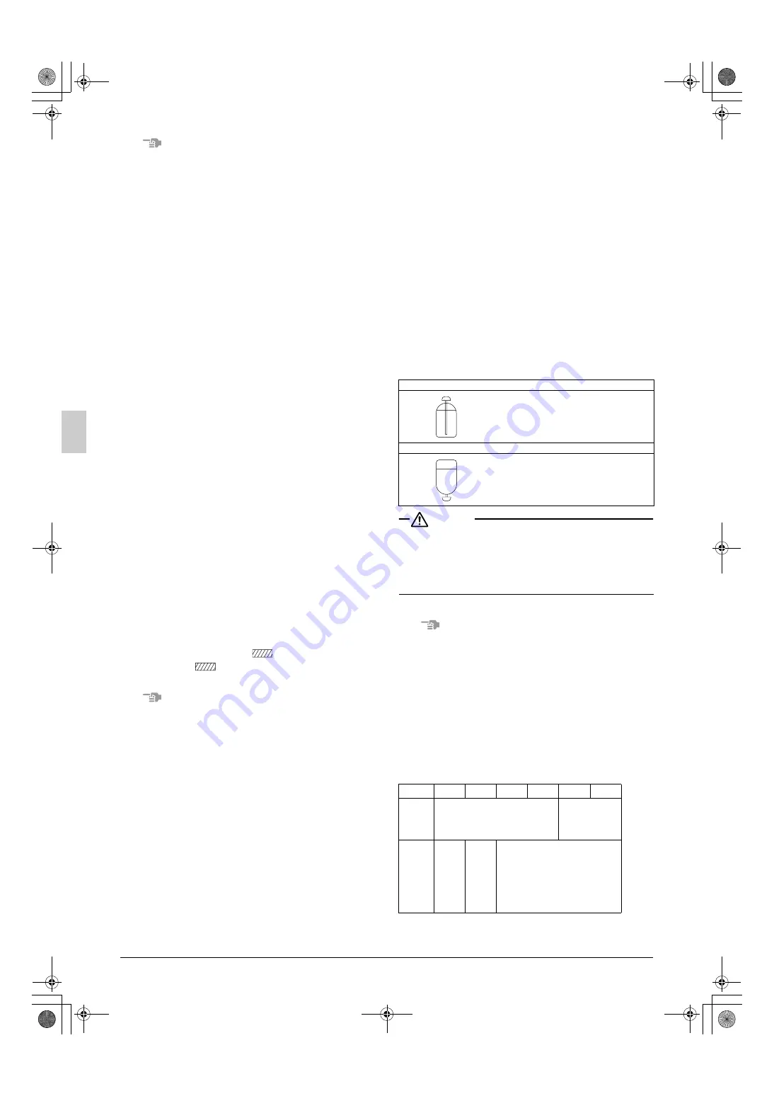
[About the refrigerant tank]
Check whether the tank has a siphon pipe before charging and place
the tank so that the refrigerant is charged in liquid form. (See the fig-
ure below.)
CAUTION
• Always use the proper refrigerant (R410A). If charged with the
refrigerant containing an improper material, it may cause an
explosion or accident.
•
R410A is a mixed refrigerant, so charging it as a gas will cause
the refrigerant composition to change, which may prevent normal
operation.
[Shutoff valve operation procedure]
When operating the shutoff valve, follow the procedure instructed below.
Note
•
Do not open the shutoff valve until “10. CHECKING OF DEVICE
AND INSTALLATION CONDITIONS” are completed. If the shutoff
valve is left open without turning on the power, it may cause refrig-
erant to buildup in the compressor, leading insulation degrada-
tion.
•
Be sure to use the correct tools.
The shutoff valve is not a back-seat type. If forced it to open, it
might break the valve body.
•
When using a service port, use the charge hose.
•
After tightening the cap, make sure no refrigerant gas is leaking.
[Tightening torque]
The sizes of the shutoff valves on each model and the tightening
torque for each size are listed in the table below.
<Size of Shutoff Valve>
With siphon pipe
Other tanks
Q8 type
Q10 type
Q12 type
Q14 type
Q16 type
Liquid
side shut-
off valve
φ
9.5
The Q12 type corresponds to the
12.7-diameter onsite piping using
the included piping.
φ
12.7
Gas side
shutoff
valve
φ
15.9
φ
19.1
φ
25.4
The Q10 type corresponds to the
22.2-diameter onsite piping using
the accessory pipe.
The Q12 ~ 16 type corresponds to
the 28.6-diameter onsite piping
using the accessory pipe.
Stand the tank upright and charge.
(The siphon pipe goes all the way inside,
so the tank does not need be put
upside-down charge in liquid form.)
Stand the tank upside-down and charge.
01_EN_3P226891-13Q.fm Page 13 Thursday, December 2, 2010 10:15 AM


