background image

11

English

Note

Open the knock holes with a hammer or the like.

After knocking out the holes, we recommend you remove any 
burrs and paint them using the repair paint to prevent rusting.

When passing wiring through the knock holes, remove burrs 
around the knock holes and protect the wiring with protective 
tape. 

(Refer to figure 20)

If small animals might enter the unit, block off any gaps (hatching 
parts in figure 20) with material (field supply).

7-4 Transmission Wiring Connection Procedure

Referring to figure 21, 22 connect the transmission wiring 
between outdoor unit and indoor unit, outdoor unit and outdoor 
unit of other system, outdoor unit and outdoor unit of same sys-
tem (only multi system) or to COOL/HEAT selector.

(Refer to figure 21)

1.

Connection example for single system

2.

Outdoor unit

3.

COOL/HEAT selector

4.

To outdoor unit of other system

5.

Match up terminal symbols. (Has polarity)

6.

Use duplex wires

7.

Indoor unit

8.

Never connect the power wire

(Refer to figure 22)

1.

Connection example for multi system

2.

Outdoor unit A (Master unit)

3.

Outdoor unit B (Sub unit)

4.

COOL/HEAT selector

5.

To indoor unit

6.

To outdoor unit of other system

All transmission wiring is to be procured on site. All wiring should 

use sheathed vinyl cord 0.75-1.25 mm

2

 or cable (duplex). (Triplex 

only for the COOL/HEAT selector.)

Transmission wiring (About the symbol 

 ~ 

, see figure 21, 22) 

should be done within the following limitations.
If they are exceeded, transmission problems may occur.

 Between outdoor unit and indoor unit

Between outdoor unit and outdoor unit of other systems

Max. wiring length

: 1,000 m

Max. total wiring length

: 2,000 m

Max. no. of branches

: 16

[Note] 
No branch is allowed 
after branch
(See figure 23)

Max. no. of outdoor units of other system 
that can be connected

: 10

(Refer to figure 23)

1.

Outdoor unit

2.

Indoor unit

3.

Branch line 1

4.

Branch line 2

5.

No branch is allowed after branch

6.

Main line

7.

Central remote controller, etc.

8.

Branch line 3

9.

Transmission wiring between outdoor unit and indoor unit

10.

Transmission wiring between outdoor unit and outdoor unit

 Between outdoor unit and outdoor unit of  same system 

(Only for multi system)

Max. wiring length

: 30 m

 Transmission wiring to COOL/HEAT selector

Max. wiring length

: 500 m

The transmission wiring inside the EL.COMPO.BOX should be 
secured using the clamp (1) as shown in figure 24.

(Refer to figure 24)

1.

In the EL.COMPO.BOX

2.

Retain to the EL.COMPO.BOX with the accessory clamp 
(1).

Outside the units, the transmission wiring must be finished simul-
taneously with the local refrigerant piping, and wound with tape 
(field supply) as shown in figure 25.

(Refer to figure 25)

1.

Liquid pipe

2.

Gas pipe

3.

Transmission wiring

4.

Insulation material

5.

Finishing tape

For multi system:
1. Transmission wiring between outdoor units in the same piping 

system must be connected to terminals Q1 and Q2 (TO MULTI 
UNIT).
Connecting the wires to the F1, F2 (TO OUT/D UNIT) termi-
nals results in system malfunction.

2. Wiring to other systems should be connected to terminals F1 

and F2 (TO OUT/D UNIT) on the PC-board of the master unit. 
The outdoor unit that connected transmission wiring to indoor 
unit is the master unit. The others are sub unit.

CAUTION

• Do not connect the power wiring to terminals for the transmission 

wiring. Doing so would destroy the entire system.

When connecting wires to the terminal block on the PC-board, too 
much heat or tightening could damage the PC-board. Attach with 
care.
See the table below for the tightening torque of the transmission 
wiring terminals.

7-5 Power Wiring Connection Procedure

Be sure to connect the power supply wiring to the power supply ter-
minal block and hold it in place using the included clamp as shown in 
the figure 26.

(Refer to figure 26)

1.

Power supply (3N~50Hz 380-415V)

2.

Earth leakage circuit breaker

3.

Branch switch, Overcurrent breaker

4.

Ground wire

5.

Attach insulation sleeves

6.

Power supply terminal block

7.

Ground terminal

8.

Clamp (1) (accessory)

The L1, L2, L3 and N phases of the power wiring should be 
secured separately to the hook using the included clamp (1).

The ground wiring should be bound to the power wiring using the 
included clamp (1) to prevent outside force from being applied to 
the terminal area.

Wire so that the ground wiring does not come into contact with the 
compressor lead wiring. If they touch, this may have an adverse 
effect on other devices.
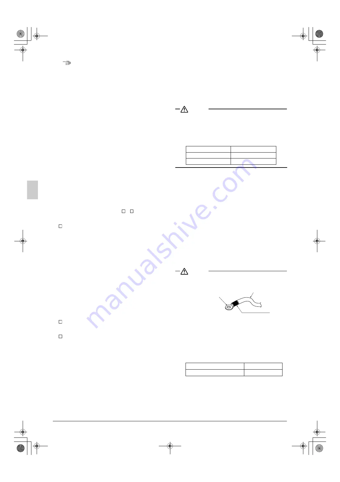
CAUTION

• Be sure to use crimp-style terminal with insulating sleeves for 

connections. (See the figure below.)

For wiring, use the designated power wire and connect firmly, 
then secure to prevent outside pressure being exerted on the ter-
minal board.

Use an appropriate screwdriver for tightening the terminal screws. 
A screwdriver with a small head will strip the head and make 
proper tightening impossible.

Over-tightening the terminal screws may break them.
See the following table for the tightening torque of the terminal 
screws.

1

3

1

2

2

3

3

Screw size

Tightening torque (N·m)

M3 ABC I/P

0.53 - 0.63

M3.5 (A1P)

0.80 - 0.96

Screw size

Tightening torque (N·m)

M8 Power terminal, ground terminal

5.5 ~7.3

Power wire

Crimp-style terminal

Insulating sleeve

01_EN_3P226891-13Q.fm  Page 11  Thursday, December 2, 2010  10:15 AM

Summary of Contents for VRVIII-Q Series

Page 1: ...B RQYQ18PY1B RQYQ20PY1B RQYQ22PY1B RQYQ24PY1B RQYQ26PY1B RQYQ28PY1B RQYQ30PY1B RQYQ32PY1B RQYQ34PY1B RQYQ36PY1B RQYQ38PY1B RQYQ40PY1B RQYQ42PY1B RQYQ44PY1B RQYQ46PY1B RQYQ48PY1B English Deutsch Fran a...

Page 2: ...00_CV_3P226891 13Q fm Page 2 Thursday December 2 2010 1 08 PM...

Page 3: ...200 300 Pattern 3 2 1 1500 3 1 4 2 5 2 mm 1000 1 0 0 0 1000 1 5 0 0 1500 1500 figure 2 2 4 5 1 8 9 10 3 6 7 11 figure 6 1 2 4 3 figure 7 1 2 3 100 100 100 2 3 100 100 100 1 2 6 3 3 4 5 figure 14 figur...

Page 4: ...6 7 8 ABC A F1 F2 F1 F2 Q1 Q2 B C 3 1 1 ABC I P A1P TOIN DUNIT TOOUT DUNIT TOMULTIUNIT F1 F2 F1 F2 F1 F2 1 2 3 4 5 6 A F1 F2 F1 F2 Q1 Q2 Q1 Q2 B C ABC I P A1P A1P TOIN DUNIT TOOUT DUNIT TOMULTIUNIT T...

Page 5: ...of Q14 16 type 1 13 2 3 4 14 5 6 7 8 9 11 10 12 15 1 2 3 4 5 6 7 8 9 10 13 13 15 16 17 14 11 12 1 6 5 4 2 3 1 2 3 4 5 figure 28 1 2 3 1 5 6 7 3 4 1 2 3 4 11 12 13 14 9 15 10 10 5 6 7 8 9 figure 31 fi...

Page 6: ...r qualified personnel to carry out installation work Do not attempt to install the air conditioner yourself Improper installation may result in water leakage electric shocks or fire Install the air co...

Page 7: ...imum refrigerant charge of a VRVIII system must be below 100kg this to be in accordance with CE requirement EN60335 2 40 standard This means that in case the total maximum refrigerant charge of the sy...

Page 8: ...l 3 Clamps 4 Accessory pipes Note Do not throw away any of the accessories until installation is com plete 2 3 Option accessory To install the outdoor units the following optional parts are also requi...

Page 9: ...to prevent snow from accumu lating on the fins 3 If condensate may drip on downstairs or walkway depending on the floor condition take a measure such as the installation of central drain pan kit sold...

Page 10: ...gen permutation or nitrogen blow when brazing Refer to figure 10 Brazing without performing nitrogen permutation or nitrogen blow into the piping will create large quantities of oxidized film on the i...

Page 11: ...ing piping between outdoor units Refer to the installation manual that comes with the kit when doing this piping work 4 Precautions when connecting piping between outdoor units In case of multi system...

Page 12: ...18 1 Do not install vertically Refer to figure 18 2 Maintain a straight portion of 500 mm or more until the split of the joint without wrapping any onsite piping around this area Over 500 mm of straig...

Page 13: ...r unit 1 8 a a u r s t i i b b a a s t r u b c d e f g h i i c d e f g h j k REFNET Header REFNET Header 1 2 3 4 5 6 1 2 3 4 5 6 7 H2 b r s u t c d e f g h 1 2 3 4 5 6 7 8 8 c d e f g h 1 2 3 4 5 6 7...

Page 14: ...920 x 15 9 19 1 22 2 28 6 34 9 41 3 19 1 25 4 28 6 34 9 54 1 9 5 12 7 15 9 19 1 12 7 15 9 19 1 22 2 Total capacity of indoor units gas pipe liquid pipe standard size max size standard size max size u...

Page 15: ...r ing and earth terminal 7 1 Power circuit safety device and cable requirements A power circuit see the following table must be provided for con nection of the unit This circuit must be protected with...

Page 16: ...be finished simul taneously with the local refrigerant piping and wound with tape field supply as shown in figure 25 Refer to figure 25 1 Liquid pipe 2 Gas pipe 3 Transmission wiring 4 Insulation mat...

Page 17: ...ve A C in figure 28 should be open or closed as shown in the table below Refer to figure 28 1 Gauge manifold 2 Nitrogen 3 Measuring device 4 R410A tank with siphon 5 Vacuum pump 6 Charge hose 7 Liquid...

Page 18: ...of a nut See 7 4 Transmission Wiring Connection Procedure 2 Make sure there is no faulty power wiring or loosing of a nut See 7 5 Power Wiring Connection Procedure 3 Has the insulation of the main pow...

Page 19: ...3 9 12 7 8 1 9 9 18 0 22 0 15 9 13 5 16 5 Hexagonal wrench 6 mm 22 5 27 5 19 1 27 0 33 0 Hexagonal wrench 8 mm 25 4 LED display h OFF i ON j Blinking Uncertain LED display H1P H2P H3P H4P H5P H6P H7P...

Page 20: ...med in recovery or other service modes About re charging of refrigerant When sizes and length of field pipings are certain figure out the re charging amount of refrigerant by calculation method of ref...

Page 21: ...Perform the refrigerant charging operation according to check operation and charge the remaining refrigerant of the additional charging amount For performing the refrigerant charging opera tion the pu...

Page 22: ...cate to open the valve of the refrigerant tank as on the right in approx 6 min after the re start Operation for re charging of refrigerant 1 60 min Contamination prevention is opearted at the same tim...

Page 23: ...t according to the list on the installation manual 1 11 Test operate again after the repair To check operate again press the RETURN button BS3 to turn the LED back to normal indications as procedure 1...

Page 24: ...it are reversed Exchange two of the three phases L1 L2 L3 and connect with the correct phase U3 Check operation has been completed normally Perform the check operation again U1 U4 LC Power is not bein...

Page 25: ...hecks After Test Run Perform the following checks after the test run is complete Record the contents of field setting Record them on the accessory REQUEST FOR THE INDI CATION label And attach the labe...

Page 26: ...results of the calcu lations in steps 1 and 2 above If the result of the above calculation exceeds the maximum con centration level then make similar calculations for the second then third smallest ro...

Page 27: ...3P226891 13Q EM10A040 1012 HT 00_CV_3P226891 13Q fm Page 6 Thursday December 2 2010 1 08 PM...

Reviews: