background image


Page | 23  


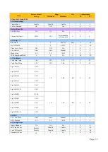
Date/Time/Schedule 


No.


Men

u


Property


Unit


Description


1


Actual Time


R/W


--


View or set the current time


2


Actual Date


R/W


--


View or set the current date


3


En Schedule


R/W


--


View or set chiller operating schedule. The 
options are as follows:  

Disable: Schedule OFF


Enable: Schedule ON


When Schedule is enabled, chiller will start 
or stop by the defined timing. 

Time Schedule 

R/W 

-- 

Set the start and stop time from Monday to 
Sunday 

Start time1: Set the first start time  

Stop time1: Set the first stop time  

Start time2: Set the second start time  

Stop time2: Set the second stop time  

Start time3: Set the third start time 

Stop time3: Set the third stop time 

Holiday 
Schedule 

R/W 

-- 

When time schedule function is enabled, 
user can use the Holiday Schedule to disable 
the chiller on a specific day 

Holiday#: Set the # holiday  

Where # = 1 to 10 

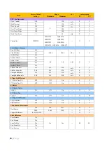
UTC diff 

R/W 

min 

View or set the UTC time difference. UTC 
refers to Universal Time Coordinate 

DLS Enable 

R/W 

-- 

View or set the daylight-saving time mode 

DLS strt Month 

R/W 

-- 

View or set the month when the daylight-
saving time mode takes effect 

DLS Strt Week 

R/W 

-- 

View or set the week when the daylight-
saving time mode takes effect 

10 

DLS End Month 

R/W 

-- 

View or set the month when the daylight-
saving time mode finishes 

11 

DLS End Week 

R/W 

-- 

View or set the week when the daylight-
saving time mode finishes 

12 

Quiet Mode 

R/W 

-- 

View or set the quiet mode 

Summary of Contents for UAA-ST3M

Page 1: ...OPERATION MANUAL AIR COOLED CHILLER SINGLE SCREW COMPRESSOR UAA ST3M OM UAA 0620 1 DAIKIN Part Number C08019049338 ...

Page 2: ......

Page 3: ...oller features 10 4 4 Main controller 11 5 OPERATING THE CONTROL SYSTEM 13 5 1 Start Stop Unit 13 5 2 Parameter Viewing and setting 14 6 UNIT PARAMETERS 32 6 1 Unit Setpoints 32 7 TROUBLESHOOTING GUIDE 40 7 1 Startup Troubleshooting Guide 40 7 2 Alarm Troubleshooting Guide 42 7 3 Alarm Clearing 73 7 4 Alarm Log 73 8 BAS INTERFACE 74 8 1 General 74 8 2 Modbus protocol 74 8 3 BACNEt protocol 78 ...

Page 4: ...troller HAZARD IDENTIFICATION INFORMATION DANGER Dangers indicate a hazardous situation which will result in death or serious injury if not avoided WARNING Warnings indicate potentially hazardous situations which can result in property damage severe personal injury or death if not avoided CAUTION Cautions indicate potentially hazardous situations which can result in personal injury or equipment da...

Page 5: ...uit boards can cause damage to the components Discharge any static electrical charge by touching the bare metal inside the control panel before performing any service work Never unplug any cables circuit board terminal blocks or power plugs while power is applied to the panel WARNIN CAUTION NOTICE This equipment generates uses and can radiate radio frequency energy and if not installed and used in...

Page 6: ...mperature is less than 43 8F or more than 44 2F LWT Chilled Evaporator leaving water temperature EWT Chilled Evaporator entering water temperature Discharge Superheat Discharge superheat is calculated using the following equation Discharge Superheat Discharge Temperature Condenser Saturated Temperature Suction Superheat SSH SSH is calculated for each circuit using the following equation SSH Suctio...

Page 7: ...her is still operating Startup and Stop is the act of starting the first compressor or fan and stopping the last compressor or fan The Delta T is the dead band on either side the setpoint in which no action is taken Stage Up Delay The time delay from the start of the first compressor to the start of the second ...

Page 8: ...s Use separate electrical conduits for this purpose Before servicing the machine in any way open the general disconnecting switch on the machine s main power supply When the machine is off but the disconnector switch is in the closed position unused circuits are live as well Never open the terminal board box of the compressors before having opened the unit s general disconnecting switch In install...

Page 9: ...ded on request The overall controls architecture uses the following One Microtech III main controller I O extension modules as needed depending on the configuration of the unit Optional BAS interface as selected Model Controller Quantity POL687 7 POL945 POL965 POL94U UAA105 UAA220 1 1 1 1 UAA245 UAA450 1 1 2 2 BAS Interface Modbus Bacnet MicroTech III Main Controller POL687 I O Extension POL965 Sy...

Page 10: ... Switch OFF Turn OFF the unit ON Turn ON the unit 2 Q1 1 SYS SW OFF Turn OFF System 1 ON Turn ON System 1 3 Q2 2 SYS SW OFF Turn OFF System 2 ON Turn ON System 2 4 CM1 Indicating working current for 1 SYS Compressor 5 CM2 Indicating working current for 2 SYS Compressor ...

Page 11: ...rol based on condenser pressure 6 Three levels of security password protection against unauthorized changing of setpoint and other control parameters 7 Pre emptive control for low evaporator pressure and high condenser pressure condition to take corrective action prior to fault trip 8 Alarm display to inform operators of warning and fault conditions All events and alarms are with time and date for...

Page 12: ...t to the site must install the controller battery by the customer service technicians before commissioning Adjust the controller time to local time is required Please refer to procedure below for battery installation in the controller 1 Power off the controller 2 Using a small screwdriver remove the front cover on the controller MT3006 POL687 70 3 Insert the battery into the compartment on the sid...

Page 13: ...arm Query Press the key to enter alarm menu 3 Shortcut key Return to main menu 4 Return Return to the upper layer menu 5 Turn Clockwise Up Page up while checking Reduce value while parameter setting Turn Anti Clockwise Down Page down while checking increase value while parameter setting Press Enter Confirm Operation ...

Page 14: ...wise until it springs up 2 3 Turn MCB Moulded Circuit Breaker Q12 at low voltage panel to ON The following main menu displays in 30 seconds 2 4 Turn Q0 Unit Switch to ON the screens display the following After the unit and water circulation started confirm whether the water system works properly If the controller does not display Auto Evap Recirc see 10 1 2 5 Turn the Q1 1 SYS SW and Q2 2 SYS SW t...

Page 15: ...Q0 UNIT SWITCH to OFF After these operations the unit will shut down automatically 5 2 Parameter Viewing and setting After entering the user password you can view and modify parameters at the user level The default user password is 1990 Parameter setting must be in accord with this operation manual Improper setting can cause erratic chiller operation and damage to the chiller Below table shows dif...

Page 16: ...the password and press the knob to confirm the entry Enter other digits in turn in the same way If the user password is correct you can view and modify parameters at the user level After you enter the password the main menu displays as below and 6 displays at the upper left corner Turn the knob clockwise The following menu display in turn ...

Page 17: ...perature in cooling mode The value range is 4 0 C 15 0 C Cool LWT 2 indicates the double setpoint temperature of leaving water in cooling mode The value range is 4 0 C 15 0 C 3 To set Cool LWT 1 or Cool LWT 2 select the item and press the knob The following interface displays Turn the knob clockwise to increase the value and turn it anticlockwise to decrease the value and press the knob to confirm...

Page 18: ...n 1 Unit Status R View the current operation status of the unit Auto Off Ice Mode Tmr Off OAT Lockout Off All Cir Disabled Off Unit Alarm Off Keypad Disable Off Remote Sw Off BAS Disable Off Unit Sw Off Time Schedule Off Test Mode Auto Noise Reduction Auto Wait For Load Auto Evap Recirc Auto Wait For Flow Auto Pumpdn Auto Max Pulldn Auto Unit Cap Lim Auto Current Lim Off Cfg Chg Rst Ctlr Off Mfg L...

Page 19: ...he unit 6 Unit Current R A View the current of the unit 7 Softload Limit R View the softload capacity limitation of the unit 8 Network Limit R View the network capacity limitation of the unit 9 Demand Limit R View the demand capacity limitation of the unit 10 Unit Mode R View the current mode of the unit 11 Control Source R W unit The options are as follows Local The unit is controlled by control ...

Page 20: ...etails parameters No Menu Description 1 Status Settings Enter the menu For details see 41 2 Set Up Enter the menu For details see 42 3 Temperatures Enter the menu For details see 43 4 Date Time Schedules Enter the menu For details see 44 45 5 Power Conservation Enter the menu For details see 45 6 Ctrlr IP Setup Enter the menu For details see 46 7 Design Conditions Enter the menu For details see 46...

Page 21: ...el Network The unit is controlled by local panel and network 6 Netwrk En SP R View the status of BAS switch 7 Netwrk Mode SP R View the mode setting of BAS 8 Netwrk Cool SP R C View the BAS cooling setpoint 9 Netwrk Ice SP R C View the BAS ice storage setpo int 10 Netwrk Cap Lim R View the network capacity limitation of the unit 11 Stg Up Dly Rem R s View remaining time before next compressor star...

Page 22: ... View the stop temperature difference 4 Stg Up DT R View the temperature difference for starting next compressor 5 Stg Dn DT R View the temperature difference for stopping next compressor 6 Max Pulldn R C min View the evaporator entering water temperature maximum pull down rate for cooling mode 7 Stg Up Delay R min View the remaining time for starting the next compressor 8 Stg Dn Delay R min View ...

Page 23: ... Setpt R C View the current actual setpoint for leaving water temperature of the evaporator 5 Outside Air R C View or set the first temperature setpoint for evaporator leaving water in cooling mode 6 Cool LWT 1 R W C View the evaporator entering water temperature maximum pull down rate for cooling mode 7 Cool LWT 2 R W C View or set the double setpoint for evaporator leaving water in cooling mode ...

Page 24: ...et the third start time Stop time3 Set the third stop time 5 Holiday Schedule R W When time schedule function is enabled user can use the Holiday Schedule to disable the chiller on a specific day Holiday Set the holiday Where 1 to 10 6 UTC diff R W min View or set the UTC time difference UTC refers to Universal Time Coordinate 7 DLS Enable R W View or set the daylight saving time mode 8 DLS strt M...

Page 25: ...l current signal Return Adjust the settings based on evaporator water temperature Oat Adjust the settings based on ambient temperature 8 Max Reset R W C View or set the maximum reset 9 Start Reset DT R W C View or set the temperature difference between evaporator entering and leaving water using Return to adjust the evaporator leaving water temperature setpoint No Menu Property Unit Description 13...

Page 26: ... No Menu Property Unit Description 1 Apply Changes R W Any changes in this menu will be effective after confirmed here 2 DHCP R W View or set the function of dynamically obtaining the controller IP address 3 Act IP R View the current IP address of the controller 4 Act Msk R View the current subnet mask of the controller 5 Act Gwy R View the current gateway of the controller 6 Gvn IP R W View or se...

Page 27: ...settings of circuit 1 and 2 For details see 9 3 3 2 3 Comp 1 2 View parameter settings for compressor 1 2 For details see 9 3 3 3 4 Condenser 1 2 View parameter settings for condenser 1 2 For details see 9 3 3 4 View Set Unit Steps Description 1 Choose View Set Circuit and press the knob to access 2 Select Circuit 1 or Circuit 2 After selecting circuit 1 or 2 then the key parameters or status of t...

Page 28: ...perheat of circuit 1 or 2 7 Oil Pressure R kPa View the oil pressure of circuit 1 or 2 8 Oil Pr Diff R kPa View the oil pressure difference between circuit 1 or 2 namely discharge pressure minus oil pressure 9 EXV Position R View the EXV opening of circuit 1 or 2 Status Settings No Menu Property Unit Description 1 Circuit Status R View the status of circuit 1 or 2 Off Ready Off Stage Up Delay Off ...

Page 29: ... 2 No Menu Property Unit Description 1 Size R View the model of the compressor 2 Run Hours R hour View the running hours of compressor 1 2 3 No Of Starts R View the number of starts of compressor 1 2 4 Capacity R View the capacity of compressor 1 2 Condenser 1 2 No Menu Property Unit Description 1 No Of Fans running R View the number of running fans of the circuit 2 No Of Fans R View the number of...

Page 30: ...rt and press the knob to access 2 Time left for each circuit will be displayed as follow No Menu Property Unit Description 1 C1 Cycle Tm Left R s View the remaining time before compressor 1 can be restarted 2 C2 Cycle Tm Left R s View the remaining time before compressor 2 can be restarted ...

Page 31: ... Choose Time Until Restart and press the knob to access 2 Time left for each circuit will be displayed as follow No Menu Property Unit Description 1 Next Maint R W View the next maintenance time 2 Support Reference R View the telephone number of technical support personnel ...

Page 32: ...ion 1 BSP version R View the BSP version BSP refers to Board Support Package The version number must be 9 20 or higher 2 App Version R View the application program version Language Selection Language Selection Steps Description 1 Choose Language Selection and press the knob to access 2 Choose the desire interface language by turning the knob anti clockwise or clockwise press the knob to confirm se...

Page 33: ...0 S S Hi Ld Stg Up 80 0 50 0 100 0 S S M Sequence 1 1 2 S S S Sequence 1 1 2 S S Auto Restart Yes No Yes S S 1 3 Temperatures Heat LWT 1 45 0 25 0 55 0 U U Heat LWT 2 45 0 25 0 55 0 U U Cool LWT 1 7 0 4 0 15 0 U U Cool LWT 2 7 0 4 0 15 0 U U Ice LWT 4 0 8 0 4 0 U U 1 4 Power Conservation Setpoint Reset None None 4 20mA ReturnOat U U Max Reset 5 0 0 0 10 0 dK U U Start Reset DT 5 0 0 0 10 0 dK U U ...

Page 34: ...5 0 dK U S C Shut Dn DT 1 5 0 0 1 7 dK U S H Shut Dn DT 2 5 0 0 2 7 dK U S Stg Up DT 0 5 0 0 1 7 dK U S Stg Dn DT 0 7 0 0 1 7 dK U S Max Pulldn 2 5 0 5 2 5 mi n U S Stg Up Delay 5 0 60 min U S Stg Dn Delay 3 3 60 min U S Strt Strt Dly 20 15 60 min S M Stop Strt Dly 5 3 20 min S M Pumpdn Press 100 0 70 0 280 0 kPa S S Pumpdn Time 60 0 180 s S S Lt Ld Stg Dn 40 0 25 0 50 0 S S Hi Ld Stg Up 80 0 50 0...

Page 35: ...Yes S S Unld Cap Sp 40 25 80 S S 3 3 Temperatures Heat LWT 1 45 0 25 0 55 0 U U Heat LWT 2 45 0 25 0 55 0 U U Cool LWT 1 7 0 4 0 15 0 U U Cool LWT 2 7 0 4 0 15 0 U U Ice LWT 4 0 8 0 4 0 U U 3 4 Date Time Schedules Actual Time h m s 0 0 0 23 59 59 U U Actual Date m d y 1 1 2000 12 31 2050 U U En Schedule Disable Disable Enable U U 3 4 1 Time Schedule From Monday To Friday Start Time1 00 00 00 00 23...

Page 36: ...Max Reset 5 0 0 0 10 0 dK U U Start Reset DT 5 0 0 0 10 0 dK U U Max Reset OAT 15 5 10 0 29 4 U U Strt Reset OAT 23 8 10 0 29 4 U U Softload En Disable Disable Enable U U Softload Ramp 20 1 60 min U U Starting Cap 40 0 20 0 100 0 U U 3 6 Configuration Apply Changes No No Yes S S M A Setting Single Single Master Auxiliary S S Number Of Ckts 1 1 2 S M Slide Pos Sens No No Yes S M Unit Model ST3 ST3 ...

Page 37: ...l Pr Diff 250 0 0 0 415 0 kPa S S Hi Disch Temp 110 0 65 0 110 0 S S Hi Cond Pr Dly 5 0 30 s S M Lo Pr Ratio Dly 90 30 300 s S M Low Disch SH 12 10 0 15 0 dK S S Low DSH SSH Set 1 0 1 0 8 5 dK S S Cool OAT Lockout 4 0 23 0 15 0 S M Heat OAT Lockout 11 0 23 0 15 0 S M Strt Time Lim 60 20 0 180 0 s S S Evap Water Frz 2 2 2 0 6 0 S M Evap Flw Proof 15 5 15 s S S Evp Rec Timeout 3 1 10 min S S Heat HP...

Page 38: ...anual S S Manual Cap 0 0 0 0 100 0 S S 50 60CompLoad2DelT 4 4 20 s M M 4 3 Condenser Cond Min Temp 36 0 26 0 43 0 S M Cond Max Temp 43 0 32 0 50 0 S M Stg On Db 0 C 4 0 1 0 10 0 dK S M Stg On Db 1 C 5 0 Stg On Db 2 C 5 5 Stg On Db 3 C 6 0 Stg On Db 4 C 6 5 Stg On Db 5 13 C 6 5 Stg Off Db 2 C 10 0 1 0 13 0 dK S M Stg Off Db 3 C 8 0 Stg Off Db 4 C 5 5 Stg Off Db 5 C 4 0 Stg Off Db 6 14 C 4 0 4 4 EXV...

Page 39: ...set 0 0 5 0 5 0 dK S S Disch Offset 0 0 De Ice 1 Offst 0 0 De Ice 2 Offst 0 0 Sld Pos Min mA 4 0 0 0 22 0 mA S S Sld Pos Max mA 20 0 0 0 22 0 mA S S CompCurrMin mA 4 0 0 0 22 0 mA S S CompCurrMax mA 20 0 0 0 22 0 mA S S 5 Time Until Restart C1 Cycle Tmr Clr Off Off On S S C2 Cycle Tmr Clr Off Off On S S 6 Alarms 6 1 Alarm Active AlmClr Off Off On N N 6 2 Alarm Log LogClr Off Off On N M 6 3 ExportH...

Page 40: ...rm Out Off Evap Pump 1 Off Evap Pump 2 Off Water Valve Off Water Ele Heater Off HR Pump Off C1 HR Ele Heater Off C2 HR Ele Heater Off 9 2 Cir 1 2 Manual Control Test Sld Load1 Off Off On S S Test Sld Load2 Off Test Sld Unld1 Off Tst Sld Assist Off Test Liq Line Off Test Liq Inj Off Test Economizr Off Test 4 Way Sv Off Test EXV Pos 0 0 0 0 100 0 S S Test Fan 1 Off Off On S S Test Fan 2 Off Test Fan...

Page 41: ...date If the difference is more than 2 7 C compressor will start automatically and accommodate load If the difference is more than 2 7 C and the compressor doesn t start please get on with the next step 2 If the controller displays OFF All Cir Disabled enter the View Set menu and check the status of the system If the system is in the following status the compressor cannot be started normally Unit s...

Page 42: ...larm log and active alarms 3 After entering the Alarm Active menu you can view the number of alarms and clear alarms See the following figure By turning the knob clockwise or anticlockwise you can select an alarm Then press the knob to view the data and time when the alarm is generated 4 Record the alarm information displayed on the controller in the following table ...

Page 43: ...sensors for entering leaving water works properly Check whether the temperature sensors for entering leaving water are correctly connected 5 UnitOffEvpEntWTempOffNormal Check whether entering water temperature sensor is working properly Check whether entering water temperature sensor wiring is correct 6 AlrmLimCtrlrCommFailOffNormal Check whether the alarm output control panel and the main control...

Page 44: ...Check that the working conditions meet the related requirements For standard cooling operation ambient temperature 5 50 C leaving water 4 35 C For low ambient temperature cooling operation ambient temperature 10 50 C leaving water 4 35 C 16 C1 2Cmp1 OffMechPressHiOffNormal Check that the working conditions meet the related requirements Refrigerant charge meets the requirement on the nameplate not ...

Page 45: ...d its wiring Check the fan speed regulating governor 22 C1 2 OffCmpCtrlrComFailOffNormal Check whether compressor control panel and the main controller are properly connected Remarks Ensure that unit is working in the designated envelope Ensure water flow is the rated water flow Ensure relative humidity if the unit operating environment should be 90 or less ...

Page 46: ...igger Action Unit immediate shutdown Reset method Manual reset Reset Condition Phase protector contact NC Close for 5 Sec Solution Check unit power supply quality Alarm No Yes Yes No Main controller has power up for 5 sec Phase protector contact Open Phase protector configuration is Single point Yes No ...

Page 47: ...rrence alarm Manual reset Case 2 Manual reset Reset Condition Water flow switch contact Close Solution Check and make sure water flow meet recommended requirement Confirm Time 15 sec Alarm Yes No Water flow switch contact Open Confirm Time 5 min No No Yes Pump is running No Yes Pump runtime 30 Sec Yes No Evap Pmp Ctrl 1 Only Water flow switch contact Open Yes Yes Yes No No Case 1 Case 2 ...

Page 48: ...method Manual reset Reset Condition Entering water temp 2 2o C Leaving water temp 2 2o C Solution Check and make sure water flow meet recommended requirement Yes No Yes Yes No Confirm Time 3 sec Alarm Evap entering leaving water temp sensor Alarm Evap entering leaving water temp 2 2o C Alarm UnitOffEvpEntWTempOffNormal UnitOffEvpLvgWTempFault Yes ...

Page 49: ...hod Manual reset Reset Condition Evap Entering water temp Evap Leaving water temp Solution Check whether both temperature sensor condition are good Check whether both sensors are inverted No No Yes Yes No Evap LWT Evap EWT 1 5 o C Alarm Evap entering leaving water temp sensor Alarm No of running compressor 1 Alarm UnitOffEvpEntWTempOffNormal UnitOffEvpLvgWTempFault Yes Confirm time 30 sec Yes No ...

Page 50: ...ution Check sensor condition wiring and connector condition Alarm Ambient temp sensor faulty Code UnitOffAmbTemp Category Critical Trigger Action Unit immediate shutdown Reset method Manual reset Reset Condition Ambient temperature in operating range Solution Check sensor condition wiring and connector condition Check operating ambient temperature Yes No Evap entering water Temp out of range Alarm...

Page 51: ...een Main controller and extension module Alarm Emergency Stop Alarm Code UnitOffEmergencyStopOffNormal Category Critical Trigger Action Unit immediate shutdown Reset method Manual reset Reset Condition Emergency stop contact Closed for 5 Sec Solution Check emergency stop switch condition Check and eliminate the cause of emergency shutdown Main controller power up time 60 Sec Alarm No Yes Yes No Ex...

Page 52: ...ction Unit immediate shutdown Reset method Manually reset Reset Condition External alarm contact Close for 5 Sec Solution Check for field wiring relay contact and control box internal wire connection Yes External Alarm contact Open Alarm Yes No External Fault Cfg Alarm Confirm Time 5 sec No No Yes ...

Page 53: ...n operating range Solution Check sensor condition wiring and connector condition Alarm Unit Power Restore Code UnitPowerRestore Category Critical Trigger Action No action Reset method Auto reset Reset Condition Evap entering water temperature in operating range Solution Check sensor condition wiring and connector condition Yes No Evap entering water Temp out of range Alarm Yes No Controller power ...

Page 54: ... operating idle Unit not allow to start Reset method Auto reset Reset Condition Ambient temperature Lockout SP 2 5 C Solution Check for ambient temperature sensor condition Check for ambient air temperature manually start unit when ambient temperature meets requirement Yes OAT Lockout SP Ambient Temperature Alarm Yes No Unit Mode Cooling No ...

Page 55: ... reset Reset Condition Communication between main controller and extension module is established for 5 sec Solution Check connection between Main controller and extension module Check extension module or main controller condition Main controller power up time 60 Sec Alarm No Yes No Yes Fan ctrl module communicate with Main controller Confirm Time 5 sec ...

Page 56: ...utdown Reset method Manual reset Reset Condition C Evap pressure Low pressure unload SP Solution Check for refrigerant leakage Check for filter drier clog Check for pressure transducer suction and discharge condition C Compressor state ON Alarm Yes No Yes Cond saturated temp 15 5 C Evap pressure low pressure unload SP Confirm Time 60 sec Yes No No No ...

Page 57: ...stem immediate shutdown Reset method Manual reset Reset Condition C Cond sat temp Cond sat temp Alarm SP Solution Check chiller operating ambient temperature Check condensing coil condition Check refrigerant charge Check condenser fan motor and blade condition Check condenser fan contactor condition C Compressor state ON Alarm Yes No Yes C Cond saturated temp Cond temp alarm SP Confirm Time 5 sec ...

Page 58: ...ction Corresponding system immediate shutdown Reset method Manual reset Reset Condition C Cond sat temp Cond sat temp Alarm SP Solution Check unit operating environment Check filter drier for clog Check possible leakage Check water flow C Compressor state ON Alarm Yes No Yes C Evap pressure Evap pressure alarm SP No No C Evap pressure Evap pressure unload SP Confirm Time Freeze time delay No Yes Y...

Page 59: ...𝑣𝑎𝑝 𝑃𝑟𝑒𝑠𝑠𝑢𝑟𝑒 𝑘𝑃𝑎 Trigger Action Corresponding system pump down shutdown Reset method Manual reset Reset Condition Cond sat temp Cond sat temp Alarm SP Solution Check refrigerant charge Check filter drier for clog Check possible leakage Check water flow C Compressor state ON Alarm Yes No Yes Actual pressure ratio PrRatio alarm SP No No Confirm Time 90 sec Yes ...

Page 60: ...mp down shutdown Reset method Manual reset Reset Condition Cond sat temp Cond sat temp Alarm SP Solution Check chiller operating ambient temperature Check condensing coil condition Check refrigerant charge Check condenser fan motor and blade condition Check condenser fan contactor condition Hi mech sw contact open Alarm Yes Yes No No Confirm Time 1 sec ...

Page 61: ...orresponding system pump down shutdown Reset method Manual reset Reset Condition Disch temp Hi disch temp SP Solution Check refrigerant charge Check filter drier for clog Check chiller operating environment C Compressor state ON Alarm Yes No Disch temp sensor Alarm No Disch temp Hi Disch temp SP Yes Alarm C Cmp OffDischTmpFault ...

Page 62: ...essure diff Discharge pressure oil pressure Trigger Action Corresponding system pump down shutdown Reset method Manual reset Reset Condition Actual oil pressure diff OilPrDiffHi SP Solution Check compressor oil filter C Compressor state ON Alarm Yes No Yes Actual oil pressure diff OilPrDiffHi SP No No Confirm Time 30 sec Yes ...

Page 63: ...Event Trigger Action Corresponding system immediate shutdown Reset method Manual reset Reset Condition Starter fault input Open Solution Check starter condition and setting Check compressor wiring PVM Config Single Point Alarm Yes No Yes Starter fault input Open No No Confirm Time 30 sec Yes ...

Page 64: ...l Category Event Trigger Action Corresponding system immediate shutdown Reset method Manual reset Reset Condition Solution Check refrigerant leakage Check suction and discharge pressure sensor condition and wiring C Compressor state ON Alarm Yes Yes Cond pressure Evap pressure No No ...

Page 65: ...ent Trigger Action Corresponding system immediate shutdown Reset method Manual reset Reset Condition Solution Check refrigerant leakage Check discharge and suction pressure transducer condition and its wiring C Compressor state ON Alarm Yes Yes Yes Evap Cond pressure 35kPa No No VFD unit No ...

Page 66: ...rigger Action Corresponding system immediate shutdown Reset method Manual reset Reset Condition Solution Check refrigerant leakage Check discharge and suction pressure transducer condition and its wiring C Compressor state ON Alarm Yes Yes Yes Evap Cond pressure 35kPa No No VFD fan control No ...

Page 67: ...hod Manual reset Reset Condition Communication between main controller and extension module is established for 5 sec Solution Check connection between Main controller and EEXV module Check EEXV module or main controller condition Main controller power up time 60 Sec Alarm No Yes No Yes EEXV module communicate with Main controller Confirm Time 5 sec ...

Page 68: ...tion Check sensor condition wiring and connector condition Alarm C Cmp Off Discharge Pressure Sensor Fault Code C Cmp OffCndPressFault Category Critical Trigger Action Unit immediate shutdown Reset method Manual reset Reset Condition Discharge pressure in operating range Solution Check sensor condition wiring and connector condition Yes No Suction pressure out of range Alarm Yes No discharge press...

Page 69: ...e Solution Check sensor condition wiring and connector condition Alarm C Cmp Off Suction Temp Sensor Fault Code C Cmp OffSuctTempFault Category Critical Trigger Action Unit immediate shutdown Reset method Manual reset Reset Condition Suction temperature in operating range Solution Check sensor condition wiring and connector condition Yes No Oil pressure out of range Alarm Yes No Suction temp out o...

Page 70: ...p OffDischTempFault Category Critical Trigger Action Unit immediate shutdown Reset method Manual reset Reset Condition Discharge temperature in operating range Solution Check sensor condition wiring and connector condition Yes No Discharge temp out of range Alarm ...

Page 71: ...ffNormal Category Critical Trigger Action Unit immediate shutdown Reset method Manual reset Reset Condition Suction pressure 35kPa Solution Check refrigerant leakage Yes No C OffStrtFailEvpPrLowLimitActive Active Alarm Occurrence counter 3 No Yes Low ambient application No Yes ...

Page 72: ...p OffMotorTempHiOffNormal Category Critical Trigger Action Unit immediate shutdown Reset method Manual reset Reset Condition Motor protection input closed Solution Check refrigerant charge overcharged Alarm Motor protection input Open No Yes Confirm Time 2 sec No Yes ...

Page 73: ...Trigger Action Unit immediate shutdown Reset method Manual reset Reset Condition Motor overload input closed Solution Check ammeter setting as per recommended in wiring diagram Check ammeter wiring and condition Check CT condition and wiring Alarm Motor Overload input Open No Yes Confirm Time 2 sec No Yes ...

Page 74: ... By turning the knob clockwise or anticlockwise you can select an alarm Then press the knob to view the data and time when the alarm is generated 7 4 Alarm Log Clear Alarm Steps Description 1 By turning the knob clockwise or anticlockwise you can select an alarm Then press the knob to view the data and time when the alarm is generated The controller can record a maximum of 50 historic alarm record...

Page 75: ...Single ACS Chiller Mode Set unsigned word R W 1 Ice 2 Cool 3 Heat 3 40035 Cool Water SetPoint 10 10 signed word R W 4 40036 Ice Water SetPoint 10 10 5 40037 Heat Water Setpoint 10 10 6 40012 Active Setpoint 10 10 R 7 40838 Control Source unsigned word R 0 Local 1 Network 8 40005 Single Master Chiller Alarm unsigned word R 0 Normal 1 Alarm 9 40006 Evap Flow Status 0 Open 1 Close 10 40013 Chiller Ac...

Page 76: ...45 41809 System 2 Oil Pressure psi 10 kPa 10 signed word R 46 41812 System 2 Comp Status unsigned word R 0 Off 1 Start 47 41966 System 2 EXV Position 48 40834 System 2 Status R 49 40023 Single Heat Recovery Outlet Water Temp 1 10 10 signed word R 50 40829 Heat Recovery Outlet Water Temp 2 10 10 51 40830 Heat Recovery Status unsigned word R 52 40331 ACS Air condition System OnOff unsigned word R W ...

Page 77: ...d Pressure psi 10 kPa 10 signed word R 86 40787 System 2 Cond Sat Temp 10 10 87 40788 System 2 Evap Pressure psi 10 kPa 10 88 40789 System 2 Evap Sat Temp 10 10 R 89 40790 System 2 Suct Temp 10 10 90 40791 System 2 Disch Temp 10 10 91 40792 System 2 Comp Starts unsigned word R 92 40793 System 2 Comp Run Hours Hour Hour 93 40794 System 2 Comp Actual Capacity 10 10 unsigned word R 94 40795 System 2 ...

Page 78: ...ED on communication module can indicate connection status LED Status Description BUS Green On Communication is normal Red On Communication error BSP Green On BSP running and communication with controller Yellow On BSP running but no communication with controller Red light flashing at 2 Hz frequency BSP error software error Red On Hardware error Red and green light shining with 1 Hz frequency inter...

Page 79: ..._state_value Single Master Chiller Status 1 Off 3 Start 4 PumpDown 5 Testing R 9 ActiveMode 2 Single Master Chiller Active Mode 1 Ice 2 Cool 3 Heat R 10 ChillerOperationMode 3 Single ACS Chiller Mode Set 1 Ice 2 cooling 3 heating R W 1 11 UnitStatus 192 Single Master Unit Actual Status precision 1 R 12 Circuit1Status 193 System 1 Actual Status precision 1 R 13 Circuit2Status 194 System 2 Actual St...

Page 80: ...rts 92 System 1 Comp Starts precision 1 R 32 Circuit2Comp1Starts 95 System 2 Comp Starts precision 1 R 33 EntEvapWaterTemp 1 analog_input Single Master Evap Inlet Water Temp precision 0 1 R ºC 34 LvgEvapWaterTempUnit 2 Evap Outlet Water Temp precision 0 1 R ºC 35 OutdoorAirTemp 5 Ambient Temp precision 0 1 R ºC 36 Circuit1Comp1DischargeTe mp 63 System 1 Disch Temp precision 0 1 R ºC 37 Circuit2Com...

Page 81: ...larm Inactive 1 Alarm Active R 55 SlaveEvapFlowStatus 32 Evap Flow Status 0 Off Inactive 1 On Active R 56 SlaveEvapPump1State 33 Evap Pump 1 Status 0 Off Inactive 1 On Inactive R 57 SlaveEvapPump2State 34 Evap Pump 1 Status 0 Off Inactive 1 On Inactive R 58 SlaveChillerStatus 10 Slave Chiller Status 1 Off 3 Start 4 PumpDown 5 Testing R 59 SlaveStatus 11 Unit Actual Status precision 1 R 60 SlaveCir...

Page 82: ... 80 System 1 Cond Sat Temp precision 0 1 R ºC 80 SlaveCir1SatEvapT 81 System 1 Evap Sat Temp precision 0 1 R ºC 81 SlaveCir2SatCondT 82 System 2 Cond Sat Temp precision 0 1 R ºC 82 SlaveCir2SatEvapT 83 System 2 Evap Sat Temp precision 0 1 R ºC 83 HPLvgWaterTemp 15 analog_input ACS Header Pipe Outlet Water Temp precision 0 1 R ºC 84 SlaveEntEvapWaterTemp 16 Slave Evap Inlet Water Temp precision 0 1...

Page 83: ... set to Single 4 Air conditioning system refers to the master and slave unit to form a dual control system Master refers to the master unit of the dual control system Slave refers to the slave unit of the dual control system 8 3 2 BACnet setup Connection methods diagram as below Diagram 1 BACnet IP Diagram 2 BACnet MS TP BSP and BUS LED on communication module can indicate connection status BUS LE...

Page 84: ...s no responsibility Models parameters and performance may change due to product improvement without further notification Please refer to the nameplate for detail The manufacturer reserves the right to revise any of the specification and design contain herein at any time without prior notice NOTE For Chiller or Component electrical non electrical end of life disposal in the interest of the environm...

Reviews: