background image

Installation manual

9

RZQG71~140L + RZQSG100~140L

Split system air conditioners

4P339538-1A – 2014.03

9.

Precautions on refrigerant piping

Do not allow anything other than the designated refrigerant to 
get mixed into the freezing cycle, such as air, etc. If any 
refrigerant gas leaks while working on the unit, ventilate the 
room thoroughly right away.

Use R410A only when adding refrigerant

Installation tools:

Make sure to use installation tools (gauge manifold, charge 
hose, etc.) that are exclusively used for R410A installations to 
withstand the pressure and to prevent foreign materials (e.g. 
mineral oils and moisture) from mixing into the system.

Vacuum pump:

Use a 2-stage vacuum pump with a non-return valve
Make sure the pump oil does not flow oppositely into the system 
while the pump is not working.
Use a vacuum pump which can evacuate to –100.7 kPa (5 Torr, 
–755 mm Hg).

During tests never pressurize the appliances with a pressure 
higher than the maximum allowable pressure (see unit name 
plate: PS).

In order to prevent dirt, liquid or dust from entering the piping, 
cure the piping with a pinch or taping.

Great caution is needed when passing copper tubes through 
walls.

Piping should be mounted so that the flare is not subjected to 
mechanical stress.

In case of simultaneous operating system
- Upward and downward piping should be performed at the 

main piping line.

- Use branch piping kit (optional) for branching refrigerant 

pipes.

Precautions to be taken. (For details, refer to the manual attached to 
branch piping kit.)

- Install the branch pipes horizontally (with a maximum 

inclination of 15°) or vertically.

- Length of branch pipe to the indoor unit should be as short as 

possible.

- Try to keep lengths of both branch pipes to the indoor unit 

equal.

When using existing refrigerant piping
Pay attention to the following points when using existing 
refrigerant piping

Perform a visual check on quality of residual oil in existing 
refrigerant piping.
This check is extremely important because using existing 
piping with deteriorated oil will cause compressor 
breakdown.
-

Put some residual oil of the pipes you want to reuse on a 
piece of white paper or on the white surface of an oil 
checking reference card and compare that oil colour with 
the circled colour of the oil checking reference card.

-

If oil colour is identical to the circled colour or darker, 
replace the piping, install new piping or clean the piping 
thoroughly.

-

If oil colour is lighter, the pipes can be reused without 
cleaning.

An oil checking reference card is indispensable for such 
evaluation and can be obtained at your dealer.

In the following situations, the existing piping should not be 
re-used and new piping should be installed.
-

If the previously used model had problems with its 
compressor (this might cause oxidised coolant oil, scale 
residue and other adverse effects).

-

If the indoor or outdoor units were disconnected from the 
piping for a long period of time (water or dirt might have 
gotten into the piping).

-

If copper piping is corroded.

Flares should not be re-used but rather new ones made in 
order to prevent leaks.

Check welded connections for gas leaks, if the local piping 
has welded connections.

Replace deteriorated insulation with new material.

9.1.

Flaring guidelines

Flares should not be re-used. New ones should be made in 
order to prevent leaks.

Use a pipe cutter and flare tool suitable for the refrigerant used.

Only use the flare nuts included with the unit. Using different 
flare nuts may cause the refrigerant to leak.

Please refer to the table for flaring dimensions and tightening 
torques (too much tightening will result in splitting the flare).

When connecting the flare nut, coat the flare inner surface with 
ether oil or with ester oil and initially tighten 3 or 4 turns by hand 
before tightening firmly.
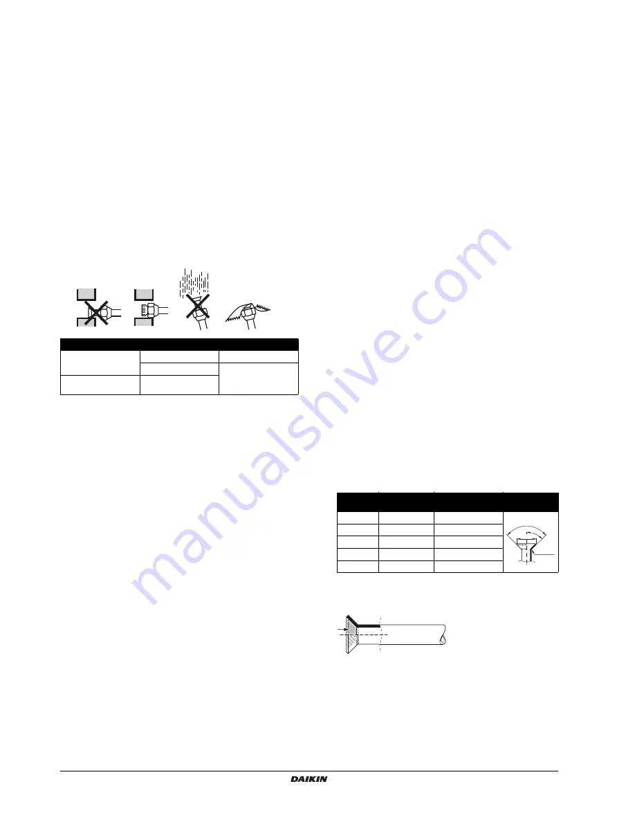
Place

Installation period

Protection method

Outdoor unit

More than a month

Pinch the pipe

Less than a month

Pinch or tape the pipe

Indoor unit

Regardless of the 

period

Piping size

(mm)

Tightening 

torque (N•m)

Flare dimensions A 

(mm)

Flare shape

(mm)

Ø6.4

15~17

8.7~9.1

Ø9.5

33~39

12.8~13.2

Ø12.7

50~60

16.2~16.6

Ø15.9

63~75

19.3~19.7

Ø19.1

90~110

23.6~24.0

A

90

2

45

2

R=0.4~0.8

Summary of Contents for SkyAir RZQG140L7V1B

Page 1: ...L RZQG71L8V1B RZQG100L8V1B RZQG125L8V1B RZQG140L7V1B RZQG71L8Y1B RZQG100L8Y1B RZQG125L8Y1B RZQG140L7Y1B RZQSG100L8V1B RZQSG125L8V1B RZQSG140L7V1B RZQSG100L8Y1B RZQSG125L8Y1B RZQSG140L7Y1B Split system...

Page 2: ...A B 1 2 4 5 H1 L3 L2 L3 L4 L2 L3 L4 L5 L6 L7 A C E B D H 1 2 3 1 50 Hz 220 240 V 3N 50 Hz 380 415 V V1 type Y1 type 1 2 4 5 A 1 A 2 100 100 100 100 1 1 2 H1 H1 H1 H2 H2 H2 L1 L1 L1 L1 L2 7 R410A R410...

Page 3: ...o com o Certificado C 09 A B C 10 Bem rk som anf rt i A og positivt vurderet af B i henhold til Certifikat C 11 Information enligt A och godk nts av B enligt Certifikatet C 12 Merk som det fremkommer...

Page 4: ...15 3 Test run 18 15 4 Precautions regarding test runs 19 15 5 Failure diagnosis at the moment of first installation 19 16 Wiring diagram 20 Thank you for purchasing this product The original instruct...

Page 5: ...an withstand its weight Insufficient strength may result in the fall of equipment and causing injury Carry out the specified installation work in consideration of strong winds typhoons or earthquakes...

Page 6: ...is advised to foresee a delay of 10 minutes for signalling the alarm in case the alarm temperature is exceeded The unit may stop for several minutes during normal operation for defrosting the unit or...

Page 7: ...or neighbours Safe places which can withstand the unit s weight and vibration and where the unit can be installed level Places where there is no possibility of flammable gas or product leak The equipm...

Page 8: ...tdoor unit In heavy snowfall areas it is very important to select an installation site where the snow will not affect the unit and set the outlet side at a right angle to the direction of the wind 6 P...

Page 9: ...let space position the units with consideration to the space required for the onsite refrigerant piping work as well Consult your dealer if the work conditions do not match those in the drawings 7 1 P...

Page 10: ...ion shall comply with applicable legislation In Europe the EN378 is the application standard that shall be used NOTICE To persons in charge of piping work Be sure to open the stop valve after piping i...

Page 11: ...el 71 100 125 140 Maximum total one way piping length a a Parenthesized figure represents the equivalent length Pair L1 size down 10 m 10 m standard 50 m 70 m 75 m 90 m size up 25 m 35 m 35 m 45 m Twi...

Page 12: ...se using existing piping with deteriorated oil will cause compressor breakdown Put some residual oil of the pipes you want to reuse on a piece of white paper or on the white surface of an oil checking...

Page 13: ...it will deteriorate the refrigerant oil 9 3 Stop valve operation Cautions on handling the stop valve Make sure to keep both stop valves open during operation The figure below shows the name of each pa...

Page 14: ...he edge and the surrounding end surfaces to prevent rusting When passing electrical wiring through the knock out holes remove any burrs from the knock out holes and wrap the wiring with protective tap...

Page 15: ...ks Use a 2 stage vacuum pump with a non return valve which can evacuate to a gauge pressure of 100 7 kPa 5 Torr absolute 755 mm Hg Connect the vacuum pump to both the service port of the gas stop valv...

Page 16: ...leak test and vacuum drying see 11 Leak test and vacuum drying on page 12 This unit requires additional charging of refrigerant according to the length of refrigerant piping connected at the site Mak...

Page 17: ...b G2 12 m 6 4 R2 0 6 kg 3 Refrigerant charge amount R R1 R2 0 5 0 6 1 1 kg Example 2 1 G1 L1 5 m G2 L2 L3 L4 17 17 20 54 2 Over 30 m a G1 5 m R1 0 0kg b G1 G2 30 5 54 30 29 6 4 R2 0 9 kg 3 Refrigerant...

Page 18: ...g on mode type RZQG71 RZQSG100 125 RZQG100 140 RZQSG140 Model Liquid piping Refrigerant piping length 5 10 m a b a For RZQG units only 3 10 m b For RZQG units only When piping length is less than 5 m...

Page 19: ...ring Secure the earth wire to the stop valve attachment plate so that it does not slide Secure the earth wire to the stop valve attachment plate one more time along with the electric wiring and the in...

Page 20: ...nsibility of the installer or user of the equipment to ensure by consultation with the distribution network operator if necessary that the equipment is connected only to a supply with a short circuit...

Page 21: ...wiring as mentioned on the wiring diagram Make sure no wiring has been forgotten and that there are no missing phases or reverse phases Is the unit properly grounded Is the wiring between units connec...

Page 22: ...or of this product only works during the initialisation stage after a power reset The reversed phase protection detector is designed to stop the product in case of an abnormality when the product is s...

Page 23: ...eat exchanger middle R6T Thermistor liquid R10T Thermistor fin RC V1B Signal receiver circuit S1PH High pressure switch TC V1B Signal transmission circuit V1R IGBT power module V1T V1B Insulated gate...

Page 24: ...4P339538 1A 2014 03 Copyright 2013 Daikin...

Reviews: