background image

English 

10

Pipe size

Tightening 

torque (ft·lbf)

Flare dimension 

A (in.)

Flare shape (in.)

φ

3/8”

24.1 - 29.4

0.504 - 0.520

A

45°± 2°

9

0°± 2°

R0.016

~0.031

φ

5/8”

45.6 - 55.6

0.760 - 0.776

Ester oil or ether oil

If you are obliged to install the unit without a torque wrench, 

• 

you may follow the installation method mentioned below.
After the work is fi nished, make sure to check that there is 
no gas leak.
When you keep on tightening the fl are nut with a spanner, 

• 

there is a point where the tightening torque suddenly in-
creases.
From that position, further tighten the fl are nut the angle 
shown below.

Pipe size

Tightening angle 

(Guideline)

Recommended arm 

length of tool (in.)

φ

3/8”

60°~90°

Approx. 7 7/8

φ

5/8”

30°~60°

Approx. 11 13/16

Disposal requirements

Dismantling of the unit,  treatment of the refrigerant, oil and 
eventual other parts should be comply the relevant local and 
national regulations.

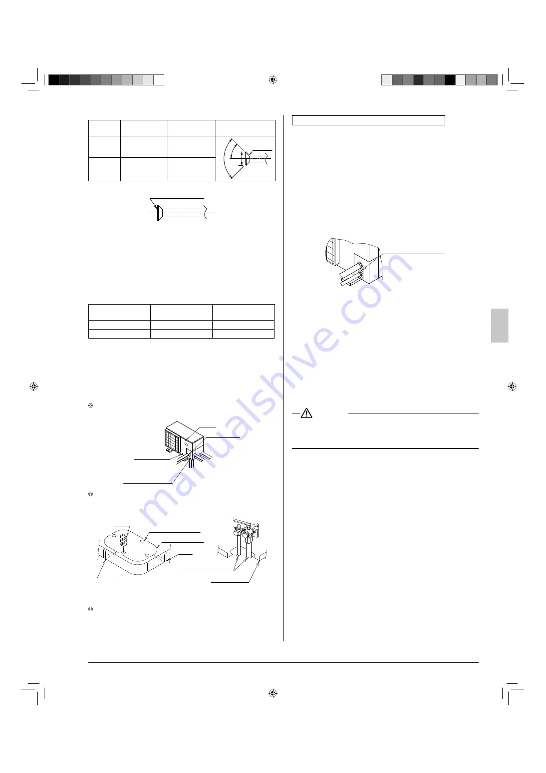
Refrigerant piping work procedure

6-4 

  The fi eld piping can be connected in three directions.

Piping cover

Screw for 
front panel

Screw for piping 
cover (front)

Front 
panel

Lateral 
direction

Front direction

Downward 
direction

  When connecting the piping downward, remove the knock-

out hole by making four holes in the middle on the each side 
of the knockout hole with a drill.

Field piping

Bottom frame

Knockout hole

Drill

Slit

Middle on the side

Slit

Then cut out the corner of the bottom frame along the slits (in 
two positions) by using a hacksaw.

  After removing the parts, it is recommended to apply repair 

paint on the edges, to prevent rusting.

Cautions on connecting the connection piping

When it is expected that water condensed in the stop valve 

• 

will reach the indoor unit through the gap between the heat 
insulating material and the piping (for example, when the 
outdoor unit is installed in a higher position than the indoor 
unit), take proper action such as caulking the connection 
area.

[Measures to prevent invasion of small creatures and litter]

Block all gaps in the piping penetration areas with putty or 

• 

heat insulating material (arranged in the local fi eld) as 
shown in the fi gure below.
(If small creatures such as insects or litter enter the outdoor 
unit, a short-circuit may be caused inside the control box.)

Putty or heat 
insulating material 
(arranged in local field)

Heat insulation of piping

6-5 

Make sure to insulate the fi eld piping (on both the liquid line 

• 

and gas line) and refrigerant branching kit.
(If they are not insulated, water leakage may be caused.)

(The maximum temperature of the piping on the gas line is 
about 248 °F during heating operation.  Use an insulation 
suffi ciently resistant to this temperature.)

Reinforce the refrigerant piping according to the installation 

• 

environment. If it is not reinforced, condensate may form on 
the surface of the insulation.

 WARNING

Make sure to insulate the fi eld piping up to the piping con-

• 

nection area inside the unit.  If the piping is exposed, dew 
condensation and burn by contact may be caused.

Airtight test and vacuum drying

6-6 

The unit has been checked for leaks by the manufacturer.
Confi rm that the valves are fi rmly closed before airtight test or 
vacuumdrying.
To prevent entry of any impurities and insure suffi cient pres-
sure resistance, always use the special tools dedicated for 
R410A.

Perform the following inspections securely after the 
piping work.

Airtight test

• 

 - Make sure to use nitrogen gas. (For the 

service port position, refer to the fi gure in “

Stop valve 

operation method

”.)

[Procedure]  Pressurize the air conditioner from the liquid 
pipe and gas pipe up to 450 psi (Make sure not to exceed 
450 psi).  When the pressure does not drop for 24 hours, the 
piping work shall be accepted.  
If the pressure drops, check for leakage positions. (Confi rm 
that there is no leakage, then release nitrogen.)

01_EN_3P281953-2A.indd   10

01_EN_3P281953-2A.indd   10

1/18/2011   9:27:20 AM

1/18/2011   9:27:20 AM

Summary of Contents for RZQ18PVJU (9)

Page 1: ...with the equipment owner Lire soigneusement ces instructions avant l installation Conserver ce manuel port e de main pour r f rence ult rieure Ce manuel doit tre donn au propri taire de l quipement Le...

Page 2: ...e area immediately Refrigerant gas may produce toxic gas if it comes in contact with fire Exposure to this gas could cause severe injury or death After completing the installation work check that the...

Page 3: ...th s protection again harmful ultraviolet radiation R410A can contribute to the greenhouse effect if it is released Therefore take proper measures to check for the tightness of the refrigerant piping...

Page 4: ...JU RZR18PVJU RZQ24PVJU RZR24PVJU RZQ30PVJU RZR30PVJU Precaution Refrigerant R410A Power 208 230V 60Hz FAQ Wall mounted Cooling MBh 18 0 24 0 a Heating MBh RZQ only 20 0 26 0 b FCQ Ceiling mounted Cool...

Page 5: ...If strong wind whose velocity is 11 mph or more blows to the outdoor unit from the air outlet side the air flow rate of the outdoor unit is reduced the outlet air is sucked again short circuit and the...

Page 6: ...space for wiring with conduit and servicing between the units A When an obstruction is present on the air inlet side When the upward area is open When one outdoor unit is installed individually 1 Whe...

Page 7: ...let side is higher than the outdoor unit There is no restriction in the height of obstruction on the air inlet side When the upward area is open When one outdoor unit is installed individually 1 L 4 o...

Page 8: ...ensional relationship between H L and A is as shown in the table below L A 0 L 1 2H 10 1 2H L H 12 When an obstruction is present also in the upward area When one outdoor unit is installed individuall...

Page 9: ...L 1 2H 10 1 2H L H 12 H L Installation is not allowed CAUTIONS ON INSTALLATION 5 Before installation confirm the strength and levelness of the foundation so that vibrations and noise are not generated...

Page 10: ...Protect the piping to prevent moisture and dusts from com ing into the piping Especially pay attention when passing the piping through a hole or connecting the end of piping to the outdoor Location W...

Page 11: ...er action such as caulking the connection area Measures to prevent invasion of small creatures and litter Block all gaps in the piping penetration areas with putty or heat insulating material arranged...

Page 12: ...refrigerant calculated by the formula below Additional charging amount Liquid piping length 0 036 Additional charging depended on type of indoor unit lb ft 0 036 A lb Indoor unit FAQ FCQ FHQ FTQ Addi...

Page 13: ...When the valve stem cannot be turned any more stop 2 turning Now the valve is open How to close the stop valve Insert a hexagon wrench into the valve stem and turn the 1 valve stem clockwise When the...

Page 14: ...smission wiring with a conduit pass through another knockout hole For protection from uninsulated live parts thread the power supply wiring or the transmission wiring through the included insulating t...

Page 15: ...ss cannot be connected to the power terminal block Slack in the electric wires may generate abnormal heat Use round pressure terminals with insulting sleeve for connection to the power terminal block...

Page 16: ...RANT PIPING WORK Piping size and heat insulation 5 Refer to 6 1 Selection of piping material 6 5 Heat insulation of piping Check of stop valve 6 Confirm that the stop valve is open on both the liquid...

Page 17: ...ation the status under execution is indicated on the remote controller 6 After the check operation make sure to close the front panel of the outdoor unit Cautions on check operation If the air conditi...

Page 18: ...g UH The transmission wiring is not connected correctly Connect correctly the transmission wiring to the F1 and F2 TO IN D UNIT terminals on the PC board A1P in the outdoor unit When nothing is displa...

Page 19: ...al amount of refrigerant lb in the system NOTE Where a single refrigerant facility is divided into 2 entirely independent refrigerant systems then use the amount of refrigerant with which each separat...

Page 20: ...3P281953 2A EM08A096D 1102 HT 00_CV_3P281953 2A indd 2 00_CV_3P281953 2A indd 2 1 20 2011 1 24 16 PM 1 20 2011 1 24 16 PM...

Reviews: