background image

5 Installation

Installation manual 

24

RWEQ96~432TAYD

 + RWEQ96~432TATJ


VRV W T-Series water-cooled system air conditioner

WARNING 


Never remove the pinched piping by brazing.
Any gas or oil remaining inside the stop valve may blow off 

the pinched piping.

6

  Make sure that no particles remain in the pipe. Blow out any 

particles with compressed air.

5 .4

Checking the refrigerant piping

5 .4 .1

About checking the refrigerant piping

Refrigerant piping works are 

finished?

The indoor units and/or 

outside unit were already 

powered ON?

Use procedure:
"Method 2: After power ON".

Finish piping work.

Use procedure:
"Method 1: Before power ON 

(regular method)".

Yes

No

No

Yes

It is very important that all refrigerant piping work is done before the 

units (outside or indoor) are powered on.
When the units are powered on, the expansion valves will initialize. 

This means that they will close. Leak test and vacuum drying of field 

piping and indoor units is impossible when this happens.
Therefore, there will be explained 2 methods for initial installation, 

leak test and vacuum drying.

Method 1: Before power ON

If the system has not yet been powered on, no special action is 

required to perform the leak test and the vacuum drying.

Method 2: After power ON

If the system has already been powered on, activate setting [2-21] 

(refer to "7.2.4 To access mode 1 or 2" on page 36). This setting will 

open field expansion valves to guarantee a R410A piping pathway 

and make it possible to perform the leak test and the vacuum drying.

NOTE 

Make sure that all indoor units connected to the outside 

unit are powered on.

NOTE 

Wait until the outside unit has finished the initialization to 

apply setting [2-21].

Leak test and vacuum drying

Checking the refrigerant piping involves:

▪  Checking for any leakages in the refrigerant piping.
▪  Performing vacuum drying to remove all moisture, air or nitrogen 

in the refrigerant piping.

If there is a possibility of moisture being present in the refrigerant 

piping (for example, water may have entered the piping), first carry 

out the vacuum drying procedure below until all moisture has been 

removed.
All piping inside the unit has been factory tested for leaks.
Only field installed refrigerant piping needs to be checked. 

Therefore, make sure that all the outside unit stop valves are firmly 

closed before performing leak test or vacuum drying.

NOTE 

Make sure that all (field supplied) field piping valves are 

OPEN (not outside unit stop valves!) before you start leak 

test and vacuuming.

For more information on the state of the valves, refer to 

"5.4.3 Checking refrigerant piping: Setup" on page 24.

5 .4 .2

Checking refrigerant piping: General 

guidelines

Connect the vacuum pump through a manifold to the service port of 

all stop valves to increase efficiency (refer to "5.4.3 Checking 

refrigerant piping: Setup" on page 24).

NOTE 

Use a 2-stage vacuum pump with a non-return valve or a 

solenoid valve that can evacuate to 500 microns or less.

NOTE 

Make sure the pump oil does not flow oppositely into the 

system while the pump is not working.

NOTE 

Do not purge the air with refrigerants. Use a vacuum pump 

to evacuate the installation.
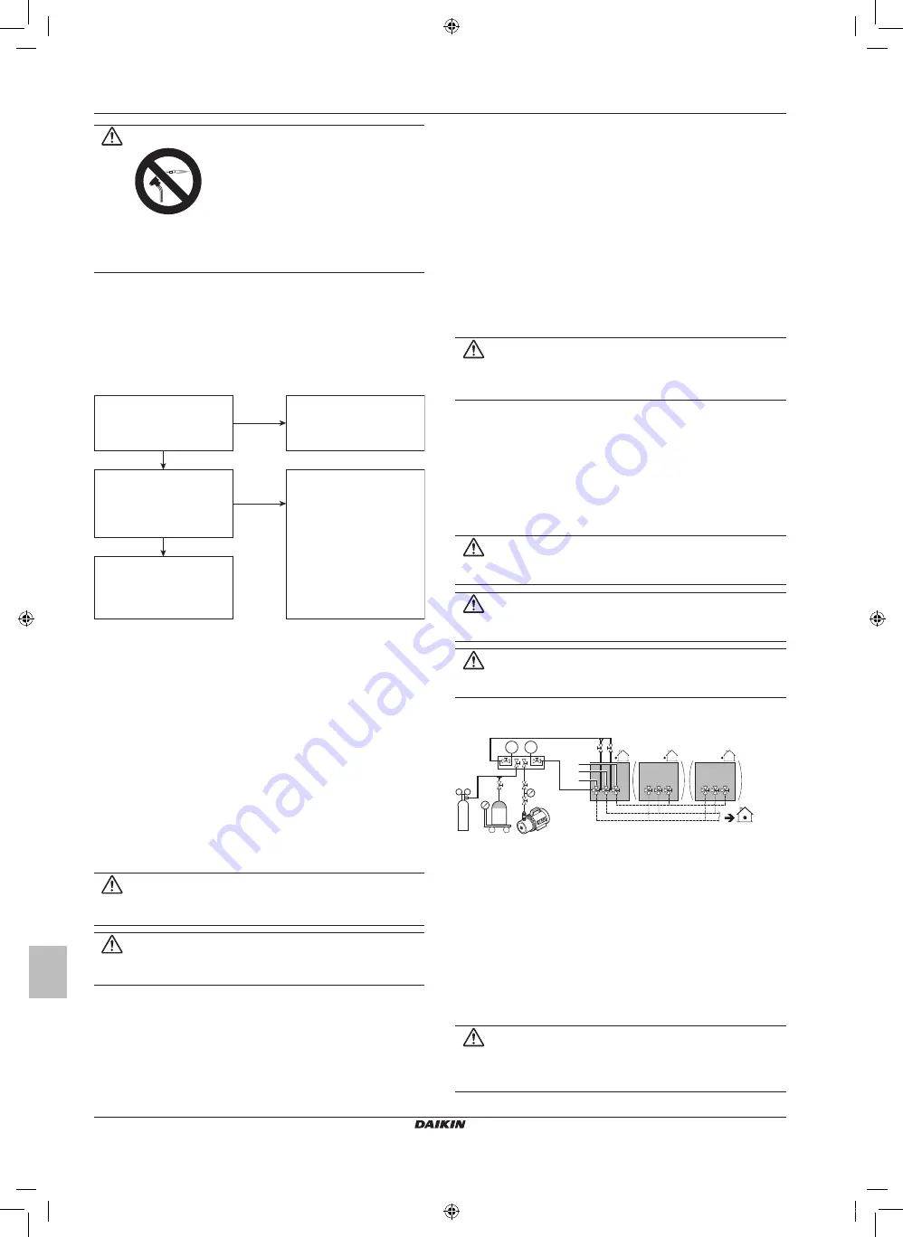
5 .4 .3

Checking refrigerant piping: Setup

p< p>

R410A

N2

C

(1)

D

b

c

e

a

g

h

f

d

A

B

a

Pressure reducing valve

b

Nitrogen

c

Weighing scales

d

Refrigerant R410A tank (siphon system)

e

Vacuum pump

f

Liquid line stop valve

g

Gas line stop valve

h

High pressure/low pressure gas line stop valve

A

Valve A

B

Valve B

C

Valve C

(1)

D

Valve D

(1) Only for heat recovery mode.

NOTE 

Do not connect the vacuum pump to the suction gas stop 

valve if the unit is intended to run in heat pump mode. This 

will increase the risk of unit failure.

01_EN_4P602454-1C.indd   24

2020/07/29   16:16:46

Summary of Contents for RWEQ96TAYD Series

Page 1: ...these instructions carefully before installation Keep this manual in a handy place for future reference This manual should be left with the equipment owner Please visit http www daikinac com com resou...

Page 2: ...frigerant piping General guidelines 24 5 4 3 Checking refrigerant piping Setup 24 5 4 4 Air tight test and vacuum drying 25 5 5 To insulate the refrigerant piping 25 5 6 Charging refrigerant 26 5 6 1...

Page 3: ...stallation could result in water leakage electric shock or fire When installing the unit in a small room take measures to keep the refrigerant concentration from exceeding allowable safety limits Exce...

Page 4: ...disturb the operation of the control system and cause the unit to malfunction d Where flammable gas may leak where there is carbon fiber or ignitable dust suspension in the air or where volatile flamm...

Page 5: ...amage the unit when removing the shrink foil with a cutter Remove the 4 bolts fixing the unit to its pallet WARNING Tear apart and throw away plastic packaging bags so that nobody especially children...

Page 6: ...0 21 1 80 26 7 90 32 2 100 37 8 110 43 3 120 48 9 60 15 6 50 10 70 21 1 80 26 7 90 32 2 In case of antifreeze usage Cooling Heating 20 6 7 60 15 6 70 21 1 80 26 7 90 32 2 100 37 8 110 43 3 120 48 9 10...

Page 7: ...tion Certain features have exclusive model rights These units are intended for indoor installation and aimed for heat pump applications including water to air The normal operating water inlet temperat...

Page 8: ...ple outside units Type Max connection ratio Types of connected indoor units When using only FXDQ FXMQ P FXAQ FXSQ07 54T When using at least one FXFQ07 09 FXZQ05T FXSQ05T All other models Single outsid...

Page 9: ...uter interface For this option 999482P3 is required which is a dedicated cable to communicate with the outside unit 4 Preparation 4 1 Overview Preparation This chapter describes what you have to do an...

Page 10: ...About safety against refrigerant leaks The installer and system specialist shall secure safety against leakage according to local regulations or standards The following standards may be applicable if...

Page 11: ...age the refrigerant oil Use only pipes which are clean inside and outside and which do not accumulate harmful sulfur oxidants dirt cutting oils moisture or other contamination Foreign materials inside...

Page 12: ...30 x 300 1 3 8 34 9 3 4 19 1 300 1 5 8 41 3 In case of heat recovery mode Unit inch mm Indoor unit capacity index Piping outer diameter size Suction gas pipe High pressure low pressure gas pipe Liquid...

Page 13: ...standard outside unit combinations Definitions Term Definition Actual piping length Pipe length between outside a and indoor units Equivalent piping length Pipe length between outside a and indoor uni...

Page 14: ...indoor units where difference from the indoor unit nearest to the outside unit is more than 130 ft 40 m please size up according to 4 3 7 Piping length requirements on page 15 c In the case of an outs...

Page 15: ...outside units exceeds 6 5 ft 2 m create a rise of 8 inch 200 mm or more in the suction gas and high low pressure gas line within a length of 6 5 ft 2 m from the kit For the gas piping both discharge...

Page 16: ...00 m If size exceeds the main pipe size due to size increase please also size up main pipe according to 4 3 2 To select the piping size on page 11 4 4 Preparing water piping 4 4 1 Water quality requir...

Page 17: ...1 4 11 5NPT Tighten securely the connection of water piping and socket with tightening torque of 220 ft lbf 300 N m or less If a large torque is applied the unit may be damaged Example 3 15 inch 80 m...

Page 18: ...flow rate through the unit To activate the variable flow system change field setting 2 24 to the applicable value See 7 2 Making field settings on page 36 NOTE Make sure that all field supplied equip...

Page 19: ...5 36 5 A 45 45 45 A RWEQ384TATJ 36 5 36 5 44 6 A 45 45 50 A RWEQ408TATJ 36 5 44 6 44 6 A 45 50 50 A RWEQ432TATJ 44 6 44 6 44 6 A 50 50 50 A RWEQ96TAYD 13 A 15 A RWEQ120TAYD 16 5 A 20 A RWEQ144TAYD 20...

Page 20: ...rigerant leakage If refrigerant gas leaks ventilate the area immediately Possible risks Excessive refrigerant concentrations in a closed room can lead to oxygen deficiency Toxic gas may be produced if...

Page 21: ...he responsibility of the installer field piping 5 3 5 Multi connection piping kit connection NOTE Improper installation may lead to malfunction of the outside unit Install the joints horizontally so t...

Page 22: ...break equipment Do NOT use flux when brazing copper to copper refrigerant piping Use phosphor copper brazing filler alloy BCuP which does not require flux Flux has an extremely harmful influence on r...

Page 23: ...ARNING Any gas or oil remaining inside the stop valve may blow off the pinched piping Failure to observe the instructions in procedure below properly may result in property damage or personal injury w...

Page 24: ...ing for any leakages in the refrigerant piping Performing vacuum drying to remove all moisture air or nitrogen in the refrigerant piping If there is a possibility of moisture being present in the refr...

Page 25: ...to 550 psi 3 8 MPa do not pressurize more than 550 psi 3 8 MPa If the pressure does not drop within 24 hours the system passes the test If there is a pressure drop check for leaks make repairs and per...

Page 26: ...the following stages 1 Determining how much you have to charge additionally 2 Charging additional refrigerant pre charging and or charging 5 6 3 To determine the additional refrigerant amount NOTE The...

Page 27: ...NFORMATION Piping length is considered by the distance from the outside unit to the farthest indoor unit Parameter C Indoor unit capacity type FXMQ type 07 09 12 15 18 24 30 36 48 54 Refrigerant amoun...

Page 28: ...5 ft Total capacity of indoor unit 104 5 Branch Selector units BS4Q54T 1 BSQ60T 1 BSQ96T 1 Indoor units FXMQ type 18 1 24 2 36 1 54 1 FXFQ type 36 2 Other 48 1 Liquid piping a 3 4 60 ft e 1 4 15 ft i...

Page 29: ...dditional refrigerant charge label provided with the unit and attach it on the back side of the front panel Perform the test procedure as described in 8 Commissioning on page 42 Charging refrigerant 5...

Page 30: ...verage subcooling 4 9 2 7 7 2 4 0 9 9 5 5 4 9 2 7 6 1 3 4 7 2 4 0 8 6 4 8 Capacity index 288 312 336 360 384 408 432 Average subcooling 9 9 5 5 7 6 4 2 6 5 3 6 7 2 4 0 8 3 4 6 9 2 5 1 9 9 5 5 a If ave...

Page 31: ...ower supply shared by another appliance Make sure to install the required fuses or circuit breakers Install power cables at least 10 ft 3 m away from televisions or radios to prevent interference Depe...

Page 32: ...be routed in conduit Be sure to follow the limits below If the unit to unit cables are beyond these limits it may result in malfunction of transmission Description Limitation Maximum wiring length 32...

Page 33: ...anch selector unit i Indoor unit j Cooling only VRV indoor unit In case of heat pump mode F1 F1 F2 F2 Q1 Q2 TO IN D UNIT TO OUT D UNIT TO MULTI UNIT F1 F2 F1 F2 F1 F2 F1 F2 F1 F2 F1 F2 F1 F2 F1 F2 Q1Q...

Page 34: ...b Fuse or circuit breaker c Ground wire d Power supply terminal block e Connect each power wire RED to L1 WHT to L2 and BLK to L3 f Ground wire GRN YLW When connecting the ground wire it is recommende...

Page 35: ...lay accordingly Failure to do so will result in unintended forced thermo off conditions NOTE In case of two or more flow switches installed with field setting 2 24 3 activated see 7 2 8 Mode 2 Field s...

Page 36: ...figure You can see the three push buttons and the three 7 segment displays and DIP switches a b c a Switch box cover b Main PCB with 3 7 segment displays and 3 push buttons c Access cover Operate the...

Page 37: ...g in mode 2 Once mode 2 is selected push BS1 for more than 5 seconds you can select the desired setting It is done by pushing BS2 Accessing the selected setting s value is done by pushing BS3 1 time T...

Page 38: ...error codes on page 46 where most relevant malfunction codes are explained Detailed information about malfunction codes can be consulted in the service manual of this unit 7 2 8 Mode 2 Field settings...

Page 39: ...nits remain ON when secondary units are OFF 2 Water pump valve control is OFF or one pump valve per system 3 One pump valve per module pump valve on secondary units are OFF when secondary units are OF...

Page 40: ...perature during heat recovery operation 2 47 Te target 0 default Auto 1 37 4 F 3 C 2 42 8 F 6 C 3 44 6 F 7 C 4 46 4 F 8 C 5 48 2 F 9 C 6 50 F 10 C 7 51 8 F 11 C 2 50 Antifreeze type setting By changin...

Page 41: ...2 3 2 74 Heat rejection cancellation setting temperature If the unit internal temperature is higher than the zero energy dissipation setting temperature the zero energy dissipation control will start...

Page 42: ...verter PCB abnormality L3 Reactor temperature rise abnormality L4 Inverter radiation fin temperature rise abnormality L5 Inverter compressor instantaneous overcurrent L8 Inverter compressor overcurren...

Page 43: ...id and gas side Damaged equipment Check the inside of the unit on damaged components or squeezed pipes Refrigerant leak Check the inside of the unit on refrigerant leakage If there is a refrigerant le...

Page 44: ...est run on page 44 to take actions for correcting the abnormality When the test operation is fully completed normal operation will be possible after 5 minutes 8 6 Correcting after abnormal completion...

Page 45: ...n 3 Steps to be taken if a freeze protection device is activated If the freeze protection device is activated during operation be sure to remove the cause before restarting the operation If the freeze...

Page 46: ...y 9 4 1 To use vacuum mode 1 When the unit is at standstill set the unit in 2 21 1 Result When confirmed the indoor and outside unit expansion valves will fully open At that moment the 7 segment displ...

Page 47: ...perature sensor malfunction R1T A4P X11A Check connection on printed circuit board or actuator HJ 01 02 03 Water system malfunction Check water pump and waterflow Check flow switch interlock connectio...

Page 48: ...U9 01 System mismatch Wrong type of indoor units combined R407C Mini split etc Indoor unit malfunction Check if other indoor units have malfunction and confirm indoor unit mix is allowed UA 18 Connec...

Page 49: ...dequate for servicing and the minimum space for ventilation is available refer to the figure below a a b b b b 1 c c b b F d 2 a 19 11 16 inch 500 mm b 13 16 inch 20 mm c 35 7 16 inch 900 mm d 11 13 1...

Page 50: ...vice port 0 32 inch flare connection C Cooling water inlet D Cooling water outlet Charge port Service port Filter Check valve Pressure relief valve Solenoid valve Capillary tube Electronic expansion v...

Page 51: ...1 2 t PS K3R M2F M1F M3F DS1 DS2 E1HC 7 8 9 10 4 2 3 1 X1M Note 2 X1A C B A X2M Note 2 X20A X37A 2 1 2 1 PS Q1DI 1 2 3 4 5 6 7 8 9 10 Z1F Y9S t A B C Power supply water control output Power supply 12...

Page 52: ...4 2 3 1 X1A X1M Note 2 C B A A B C t t t Z1F PS Z1F X3A X1A 1 2 F1S K1R X2A X3M MS 3 V1R Y9S X15A DS1 DS2 U U U E U Cool Heat Air control Cool heat selector Control box Fan Power supply water control...

Page 53: ...4P602454 1C 2020 08 Daikin Texas Technology Park 19001 Kermier Road Waller TX 77484 U S A 00_CV_4P602454 1C indd 2 2020 07 30 14 32 15...

Reviews: