
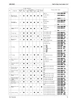
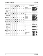
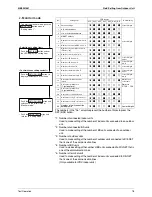
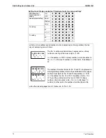


Field Setting from Outdoor Unit
SiBE341001
85
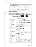
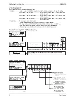
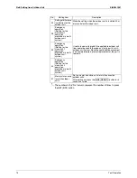
Test Operation
g
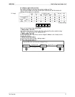
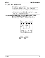
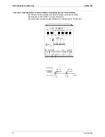
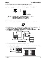
Set cool/heat at all outdoor unit systems simultaneously for each outdoor unit external control adaptor
by using the central remote controller.
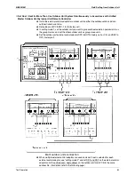
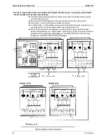
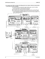
Install the outdoor unit external control adaptor (optional accessory) onto the outdoor-
outdoor, indoor-outdoor, or indoor-indoor transmission line.
Use "setting mode 1" and set all outdoor units to SLAVE.
Set the outdoor unit external control adaptor SS1 to BOTH (factory set) or C/H and set SS2 to ON.
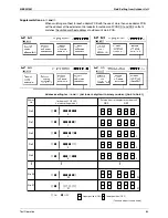
Use "setting mode 2" and set DS1 and DS2 on the outdoor unit external control adaptors
and the unified heat/cool address on the outdoor unit main PCB to the same address. (The
factory set addresses are all "0".)
Summary of Contents for RQYQ140-180PY1
Page 216: ...Piping Diagrams SiBE341001 207 Appendix 1 2 BS Unit BSVQ100 160 250PV1 4D057985B...
Page 217: ...SiBE341001 Piping Diagrams Appendix 208 BSV4Q100PV1 3D064148...
Page 218: ...Piping Diagrams SiBE341001 209 Appendix BSV6Q100PV1 3D064149...
Page 220: ...Wiring Diagrams for Reference SiBE341001 211 Appendix 2 2 BS Unit BSVQ100 160 250PV1 3D055928C...
Page 221: ...SiBE341001 Wiring Diagrams for Reference Appendix 212 BSV4Q100PV1 3D063928B...
Page 222: ...Wiring Diagrams for Reference SiBE341001 213 Appendix BSV6Q100PV1 3D063929B...
Page 223: ...SiBE341001 Option List Appendix 214 3 Option List 3 1 Option Lists Outdoor Unit 3D066354...