


SiUS371901E
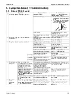
Symptom-based Troubleshooting
Service Diagnosis
230
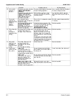
Symptom
Supposed Cause
Countermeasure
11 The system
produces
sounds.
Indoor unit
Immediately after turning ON
the power supply, indoor unit
produces ringing sounds.
These are operating sounds of the
electronic expansion valve of the
indoor unit.
Normal operation.
This sound becomes low after a
lapse of approximately one minute.
Indoor and outdoor units
Hissing sounds are
continuously produced while in
cooling or defrost control.
These sounds are produced from
gas (refrigerant) flowing
respectively through the indoor and
outdoor units.
Normal operation.
Indoor and outdoor units
Hissing sounds are produced
immediately after the startup or
stop of the system, or the
startup or stop of defrost
control.
These sounds are produced when
the gas (refrigerant) stops or
changes flowing.
Normal operation.
Indoor unit
Faint sounds are continuously
produced while in cooling
operation or after stopping the
operation.
These sounds are produced from
the drain discharge device in
operation.
Normal operation.
Indoor unit
Creaking sounds are produced
while in heating operation or
after stopping the operation.
These sounds are produced from
resin parts expanding and
contracting with temperature
changes.
Normal operation.
Indoor unit
Sounds like trickling or the like
are produced from indoor units
in the stopped state.
On
VRV
systems, these sounds are
produced when other indoor units in
operation. The reason is that the
system runs in order to prevent oil
or refrigerant from dwelling.
Normal operation.
Outdoor unit
Pitch of operating sounds
changes.
The reason is that the compressor
changes the operating frequency.
Normal operation.
12 Dust comes out
from the system.
Dust comes out from the
system when it restarts after
the stop for an extended period
of time.
Dust, which has deposited on the
inside of indoor unit, is blown out
from the system.
Normal operation.
13 Odors come out
from the system.
In operation
Odors of room, cigarettes or else
adsorbed to the inside of indoor unit
are blown out.
The inside of the indoor unit should
be cleaned.
14 Outdoor fan
does not rotate.
In operation
The reason is that fan revolutions
are controlled to put the operation to
the optimum state.
Normal operation.
15 LCD display
88
appears on the
remote
controller.
Immediately after turning ON
the power supply
The reason is that the system is
checking to be sure the remote
controller is normal.
Normal operation.
This code is displayed for a period
of approximately one minute at
maximum.
16 The outdoor unit
compressor or
the outdoor fan
does not stop.
After stopping operation
It stops in order to prevent oil or
refrigerant from dwelling.
Normal operation.
It stops after a lapse of
approximately 5 to 10 minutes.
17 The outdoor gets
hot.
While stopping operation
The reason is that the compressor
is warmed up to provide smooth
startup of the system.
Normal operation.
18 Hot air comes
out from the
system even
though it stops.
Hot air is felt while the system
stops.
On
VRV
systems, small quantity of
refrigerant is fed to indoor units in
the stopped state when other indoor
units are in operation.
Normal operation.
19 The system does
not cool air well.
The system is in dry operation. The reason is that the dry operation
serves not to reduce the room
temperature where possible.
Change the system to cooling
operation.
Summary of Contents for REYQ72-456XATJU
Page 415: ...SiUS371901E Wiring Diagrams Appendix 402 REYQ144 168XATJU 2D119206A ...
Page 416: ...Wiring Diagrams SiUS371901E 403 Appendix REYQ72 96 120XAYDU 2D119207B ...
Page 417: ...SiUS371901E Wiring Diagrams Appendix 404 REYQ144 168XAYDU 2D119208B ...
Page 418: ...Wiring Diagrams SiUS371901E 405 Appendix REYQ72 96 120 144 168XAYCU 2D119209A ...
Page 421: ...SiUS371901E Wiring Diagrams Appendix 408 FXZQ05 07 09 12 15 18TAVJU 3D110443A ...
Page 423: ...SiUS371901E Wiring Diagrams Appendix 410 FXEQ07 09 12 15 18 24PVJU 3D098557A ...
Page 426: ...Wiring Diagrams SiUS371901E 413 Appendix FXMQ07 09 12 15 18 24 30 36 48 54PBVJU 3D093209B ...
Page 428: ...Wiring Diagrams SiUS371901E 415 Appendix FXHQ12 24 36MVJU 3D048116C ...
Page 429: ...SiUS371901E Wiring Diagrams Appendix 416 FXAQ07 09 12 18 24PVJU C 3D075354D ...
Page 435: ...SiUS371901E Wiring Diagrams Appendix 422 VAM1200GVJU 3D073270D ...
Page 437: ...SiUS371901E Wiring Diagrams Appendix 424 1 4 2 Multi Branch Selector Unit BS4Q54TVJ 3D089123B ...
Page 438: ...Wiring Diagrams SiUS371901E 425 Appendix BS6 8Q54TVJ 2D089122B ...
Page 439: ...SiUS371901E Wiring Diagrams Appendix 426 BS10 12Q54TVJ 2D089121B ...
Page 440: ...Revision History Month Year Version Revised contents 04 2019 SiUS371901E First edition ...


