


SiUS371901E
Field Settings for Outdoor Unit
Field Settings and Test Operation
206
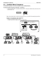
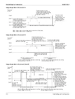
Next time graph shows the different steps during the power transistor check mode.
Switching sequence during power transistor check mode:
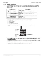
[2-29]: Capacity
priority
When the night-time low noise operation is in use, performance of system might drop because airflow
rate of outdoor unit is reduced.
Default value: 0. Capacity priority cannot be used.
Field setting 1: Capacity priority can temporary cancel the night-time low noise operation. Capacity
priority can be initiated when certain operation parameters approach the safety setting:
Raise in high pressure during cooling.
Drop in low pressure during heating.
Raise of discharge pipe temperature.
Raise of inverter current.
Raise of fin temperature inverter PCB.
Power transistor check mode REYQ-XA
disconnect fasten U/V/W from compressor!
Step 1:
Set 2-28
0 1
Press RETURN
twice
Step 2:
Set 2-28
1 0
Press RETURN
twice
Check
1
Check
2
Check
3
Magnet
switch
K1M
ON
Magnet
switch
K1M OFF
Voltage
output
U/V/W
Voltage
output
U/V/W
Frequency: 10 Hz
note
∗
6 sec
3 sec
3 sec
30 sec
Check 4
Check
5
Check 1
: AC power input :
terminal L1B, L2B, L3B at REYQ72-120XATJU (208/230 V unbalance maximum 2%).
terminal L1D, L2D, L3D at REYQ144/168XATJU (208/230 V unbalance maximum 2%).
terminal L1B, L2B, L3B at REYQ-XAYDU (460 V unbalance maximum 2%).
terminal L1B, L2B, L3B at REYQ-XAYCU (575 V unbalance maximum 2%).
Check 2
: DC voltage :
connector X6A increase to ±260 VDC at REYQ72-120XATJU.
"C+, C-" on inverter PCB from opening hole increase to ±260 VDC at REYQ144/168XATJU.
connector X5A increase to ±600 VDC at REYQ-XAYDU.
connector X5A increase to ±750 VDC at REYQ-XAYCU.
Check 3
: DC = 1.42 x VAC power supply :
connector X6A at REYQ72-120XATJU.
"C+, C-" on inverter PCB from opening hole at REYQ144/168XATJU.
connector X5A at REYQ-XAYDU.
connector X5A at REYQ-XAYCU.
Check 4
: AC U/V/W 10 Hz intermediate :
check difference within 10 V (at fasten U/V/W)
Check 5
: Voltage drop (discharge capacitors DC)
Check DC voltage :
connector X6A increase to ±260 VDC at REYQ72-120XATJU.
"C+, C-" on inverter PCB from opening hole increase to ±260 VDC at REYQ144/168XATJU.
connector X5A increase to ±600 VDC at REYQ-XAYDU.
connector X5A increase to ±750 VDC at REYQ-XAYCU
note : Actual voltage value depends on multimeter characteristics.
∗
±57 VAC at REYQ-XATJU. ±115 VAC at REYQ-XAYDU. ±143 VAC at REYQ-XAYCU.
Summary of Contents for REYQ72-456XATJU
Page 415: ...SiUS371901E Wiring Diagrams Appendix 402 REYQ144 168XATJU 2D119206A ...
Page 416: ...Wiring Diagrams SiUS371901E 403 Appendix REYQ72 96 120XAYDU 2D119207B ...
Page 417: ...SiUS371901E Wiring Diagrams Appendix 404 REYQ144 168XAYDU 2D119208B ...
Page 418: ...Wiring Diagrams SiUS371901E 405 Appendix REYQ72 96 120 144 168XAYCU 2D119209A ...
Page 421: ...SiUS371901E Wiring Diagrams Appendix 408 FXZQ05 07 09 12 15 18TAVJU 3D110443A ...
Page 423: ...SiUS371901E Wiring Diagrams Appendix 410 FXEQ07 09 12 15 18 24PVJU 3D098557A ...
Page 426: ...Wiring Diagrams SiUS371901E 413 Appendix FXMQ07 09 12 15 18 24 30 36 48 54PBVJU 3D093209B ...
Page 428: ...Wiring Diagrams SiUS371901E 415 Appendix FXHQ12 24 36MVJU 3D048116C ...
Page 429: ...SiUS371901E Wiring Diagrams Appendix 416 FXAQ07 09 12 18 24PVJU C 3D075354D ...
Page 435: ...SiUS371901E Wiring Diagrams Appendix 422 VAM1200GVJU 3D073270D ...
Page 437: ...SiUS371901E Wiring Diagrams Appendix 424 1 4 2 Multi Branch Selector Unit BS4Q54TVJ 3D089123B ...
Page 438: ...Wiring Diagrams SiUS371901E 425 Appendix BS6 8Q54TVJ 2D089122B ...
Page 439: ...SiUS371901E Wiring Diagrams Appendix 426 BS10 12Q54TVJ 2D089121B ...
Page 440: ...Revision History Month Year Version Revised contents 04 2019 SiUS371901E First edition ...


