


SiUS371901E
Outline of Control (Indoor Unit)
Functions and Control
146
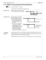
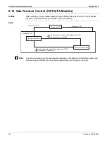
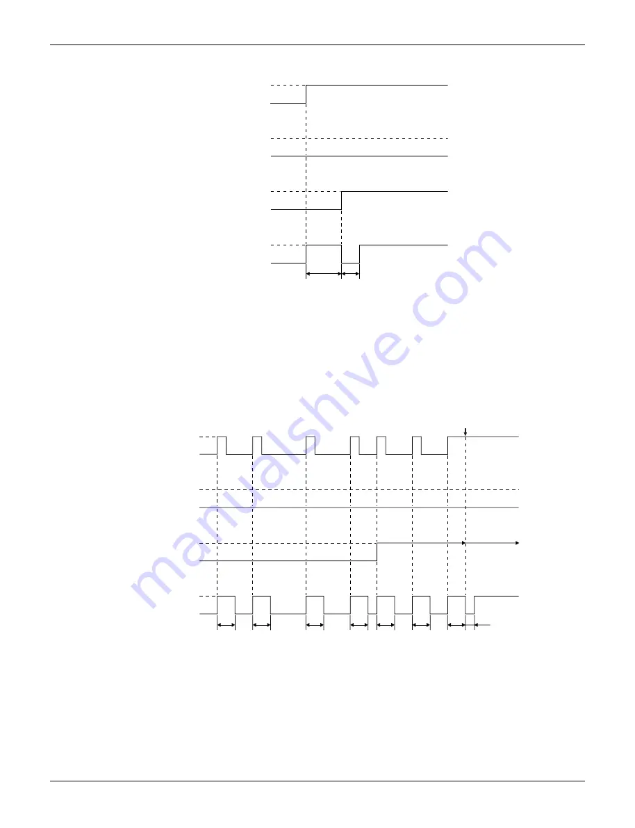
9.5.3 If the Float Switch is OFF with the Thermostat OFF in Cooling Operation
•
When the float switch turns OFF, the drain pump turns ON simultaneously.
•
If the float switch remains OFF even after the residual operation of the drain pump has ended,
the error code
A3
is displayed on the remote controller.
•
The drain pump turns OFF once residual operation has ended, then turns ON again after 5
seconds.
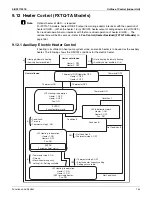
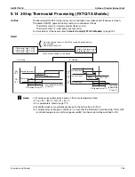
9.5.4 If the Float Switch Turns OFF and ON Continuously, or the Float Switch
Turns OFF While AF Displayed
•
When the float switch turns OFF, the drain pump turns ON simultaneously.
∗
1: If the float switch continues to turn OFF and ON 5 times consecutively, it is judged as a drain
system error and the error code
AF
is displayed on the remote controller.
∗
2: The drain pump continues to turn ON/OFF in accordance with the float switch ON/OFF even
after
AF
is displayed on the remote controller.
∗
3: While the error code
AF
is displayed, if the float switch remains OFF even after the residual
operation of the drain pump has ended, the error code
A3
will be displayed on the remote
controller.
OFF
OFF
ON
ON
ON
OFF
ON
OFF
5 min. 5 sec.
Float switch
Error display
Thermostat
(running)
Drain pump
A3
OFF
OFF
ON
ON
ON
OFF
ON
OFF
5 min.
5 min.
5 min.
5 min.
5 min.
5 min.
5 sec.
5 min.
1st
2nd
3rd
4th
5th
AF
A3
Float switch
Error display
Thermostat
(running)
Drain pump
}
∗
1
∗
3
}
∗
2
Summary of Contents for REYQ72-456XATJU
Page 415: ...SiUS371901E Wiring Diagrams Appendix 402 REYQ144 168XATJU 2D119206A ...
Page 416: ...Wiring Diagrams SiUS371901E 403 Appendix REYQ72 96 120XAYDU 2D119207B ...
Page 417: ...SiUS371901E Wiring Diagrams Appendix 404 REYQ144 168XAYDU 2D119208B ...
Page 418: ...Wiring Diagrams SiUS371901E 405 Appendix REYQ72 96 120 144 168XAYCU 2D119209A ...
Page 421: ...SiUS371901E Wiring Diagrams Appendix 408 FXZQ05 07 09 12 15 18TAVJU 3D110443A ...
Page 423: ...SiUS371901E Wiring Diagrams Appendix 410 FXEQ07 09 12 15 18 24PVJU 3D098557A ...
Page 426: ...Wiring Diagrams SiUS371901E 413 Appendix FXMQ07 09 12 15 18 24 30 36 48 54PBVJU 3D093209B ...
Page 428: ...Wiring Diagrams SiUS371901E 415 Appendix FXHQ12 24 36MVJU 3D048116C ...
Page 429: ...SiUS371901E Wiring Diagrams Appendix 416 FXAQ07 09 12 18 24PVJU C 3D075354D ...
Page 435: ...SiUS371901E Wiring Diagrams Appendix 422 VAM1200GVJU 3D073270D ...
Page 437: ...SiUS371901E Wiring Diagrams Appendix 424 1 4 2 Multi Branch Selector Unit BS4Q54TVJ 3D089123B ...
Page 438: ...Wiring Diagrams SiUS371901E 425 Appendix BS6 8Q54TVJ 2D089122B ...
Page 439: ...SiUS371901E Wiring Diagrams Appendix 426 BS10 12Q54TVJ 2D089121B ...
Page 440: ...Revision History Month Year Version Revised contents 04 2019 SiUS371901E First edition ...


