14
Not recommendable but in case of emergency
You must use a torque wrench but if you are obliged to install the unit without
a torque wrench, you may follow the installation method mentioned below.
After the work is finished, make sure to check that there is no gas leak.
When you keep on tightening the flare nut with a spanner, there is a
point where the tightening torque suddenly increases. From that posi-
tion, further tighten the flare nut the angle shown below:
(in.)
Disposal requirements
Dismantling of the unit, treatment of the refrigerant, oil and eventual
other parts, should be done in accordance with the relevant local and
national regulations.
6-5 Pipe insulation
After finishing the leak test and vacuum drying, the piping must be insu-
lated. Take into account the following points:
•
Make sure to insulate the connection piping and refrigerant branch
kits entirely.
•
Be sure to insulate the liquid-side, suction gas-side and discharge
gas-side piping for the inter-unit piping and the refrigerant branch
kits. For multiple outdoor units, always insulate the oil pressure
equalizer.
Not insulating them may cause leaking. (The gas piping can reach
temperatures of 250°F. Be sure the insulation used can withstand
such temperatures.)
•
If you think the humidity around the cooling piping might exceed
86°F and RH80%, reinforce the insulation on the cooling piping (at
least 13/16” thick). Condensation might form on the surface of the
insulation.
•
If there is a possibility that condensation on the stop valve might drip
down into the indoor unit through gaps in the insulation and piping
because the outdoor unit is located higher than the indoor unit, etc.,
this must be prevented by caulking the connections, etc.
(Refer to figure 11)
1.
Liquid line stop valve
2.
Suction gas line stop valve
3.
Discharge gas line stop valve
4.
Outer-to-inner interconnecting piping
5.
Caulking treatment, etc.
6.
Heat insulator
7.
Oil-equalizing line stop valve
8.
Oil-equalizing line
CAUTION
Be sure to insulate local pipes, as touching them can cause burns.
6-6 Additional refrigerant charge
NOTE
Refrigerant cannot be charged until field wiring has been completed.
Refrigerant may only be charged after performing the leak test and
the vacuum drying (see above).
When charging a system, care shall be taken that its maximum
permissible charge is never exceeded, in view of the danger of liq-
uid hammer.
Charging with an unsuitable substance may cause explosions and
accidents, so always ensure that the appropriate refrigerant
(R410A) is charged.
Refrigerant containers shall be opened slowly.
Always use protective gloves and protect your eyes when charging
refrigerant.
TO AVOID COMPRESSOR BREAKDOWN. DO NOT CHARGE THE
REFRIGERANT MORE THAN THE SPECIFED AMOUNT TO RAISE
THE CONDENSING PRESSURE.
•
This outdoor unit is factory charged with refrigerant and depending
on pipe sizes and pipe lengths some systems require additional
charging of refrigerant.
•
Charge the refrigerant to the liquid pipe in its liquid state. Since
R410A is a mixed refrigerant, its composition changes if charged in
a state of gas and normal system operation would no longer be
assured.
•
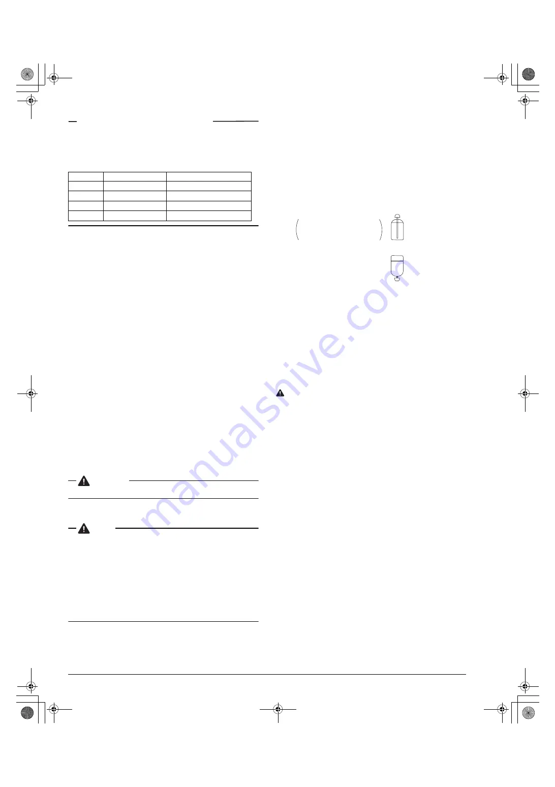
Before filling, check whether the tank has a siphon attached or not.
How to fill a tank with a siphon attached.
Other ways of filling the tank
•
Determine the amount of refrigerant to be added by referring to the
table, write it down on the included “Added Refrigerant” plate and
attach it to the rear side of the front cover.
Note: refer to the example of connection for the amount to be added.
•
After the vacuum drying is finished, charge the additional refrigerant
in its liquid state through the liquid stop valve service port. Taking
into account following instructions:
1.
Check that gas and liquid stop valves are closed.
2.
Charge the specified weight of refrigerant.
•
If the outdoor unit is not in operation and the total amount cannot be
charged, follow the procedures for additional refrigerant charge
shown below.
•
Make sure to use installation tools you exclusively use on R410A
installations to withstand the pressure and to prevent foreign mate-
rials from mixing into the system.
NOTE
•
Procedures for charging additional refrigerant.
One outdoor unit installed:
(Refer to figure 12)
1.
Pressure reducing valve
2.
Nitrogen
3.
Tank
4.
Siphon system
5.
Measuring instrument
6.
Vacuum pump
7.
Valve A
8.
Valve B
9.
Suction gas line
10.
Liquid line
11.
Discharge gas line
12.
Stop valve service port
13.
Charge hose
14.
Indoor unit
15.
BS unit
16.
Outdoor unit
17.
Dotted lines represent field supply piping
18.
Oil-equalizing line
19.
Valve C
20.
To indoor unit
Pipe size
Further tightening angle
Recommended arm length of tool
φ
3/8”
60 to 90 degrees
Approx. 7-7/8
φ
1/2”
30 to 60 degrees
Approx. 9-13/16
φ
5/8”
30 to 60 degrees
Approx. 11-13/16
φ
3/4”
20 to 35 degrees
Approx. 17-3/4
There is a siphon tube
inside, so there is no need
to turn the tank upside-down.
Fill with the tank upright.
Fill with the tank upside-down.
01_EN_3P114261-10Y.fm Page 14 Thursday, June 16, 2005 3:14 PM


