


IM 1272 • OPTILINE VERTICAL FAN COILS 8
www.DaikinApplied.com
Operating Instructions
Operating Instructions
CAUTION
Equipment damage due to loose fasteners represents improper start-up
and equipment abuse. It is not covered by the warranty.
Turn ON the disconnect switch located behind the fan
enclosure cover to the “On” position.
Standard Thermostat Digital
Programmable Thermostat
Select the mode, heating or cooling by pressing the “Mode”
button. Adjust the setpoint to desired temperature setting using
the up/down arrow buttons. Toggle the “Fan” button between
auto and run. In auto mode, the fan speed will vary based on
the difference between room temperature and room setpoint.
This is the most economical operating mode. In “Run”
mode, the fan will operate a predetermined speed set in the
“Engineering parameters”.
The “On/Off” button turns the unit ON or OFF. The thermostat
is pre-programmed which can be altered and programmed
for 5/2 day, 5, 1, 1 and 7 day. The battery back-up lasts for
5 years. See thermostat operating instructions for further
information. Refer to thermostat operating instructions for
other thermostats used.
NOTE:
The thermostat must have 0-10VDC fan signal to
control fan speed. A motor speed board model SPDM
will allow the contractor to adjust the maximum fan
speed if the factory set point is not suitable. If a
thermostat with a 3-speed fan switch is used, a digital
to analogue interface board model EVO/10Y-4Spd
must be used to convert the fan signal to a 0-10VDC.
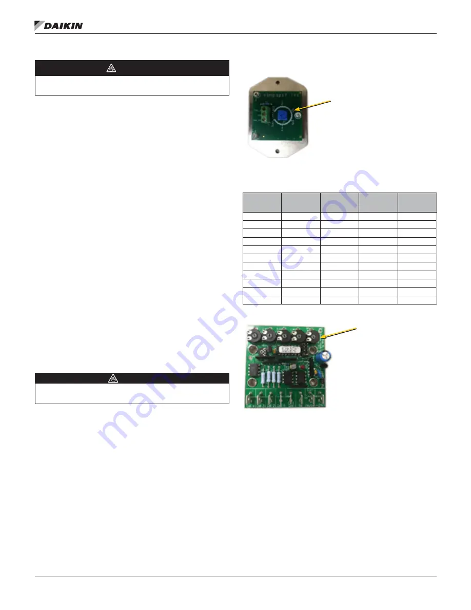
Adjusting the Maximum CFM
WARNING
If the maximum CFM is adjusted to a value above the design airflow,
excessive air noise could occur
The maximum CFM is factory set to the closest nominal
design CFM, (300, 400, 600, 800, 1000 or 1200), but can be
field adjusted if needed. With the 0-10VDC thermostat fan
signal, the max CFM can be adjusted by adjusting the blue
knob on the EBM fan board in the electrical box. See Fig. 1
and reference Table 1. To increase the maximum CFM, turn
the adjustment clockwise toward 100% and to reduce the
maximum CFM, adjust counter clock-wise toward 0%. The
chart below indicates the percent flow, CFM, relative to cabinet
size and external static pressure.
If a 3 speed fan control thermostat is used, the CFM for each
speed is factory set to be 50% on low speed, 75% on medium
speed, and 100% on high speed. Each motor speed CFM may
be adjusted by turning the adjustment pots on the EVO board.
Call 1=low speed, call 2=medium speed and call 3=high speed.
See Fig. 2
Figure 1: EVO 3 Spd Fan CFM Adjustment Board
Table 2: EBM Fan Speed Controller Setting Reference
Cabinet Size
CFM
Dial Position
@ free blow
Dial
Position@
0 .2"
ESP
Dial
Position@
0 .4"
ESP
03 – 04
200
50%
—
—
03 – 04
300
60%
70%
—
03 – 04
400
80%
90%
—
06 – 08
500
50%
60%
70%
06 – 08
600
60%
70%
80%
06 – 08
700
70%
80%
90%
06 – 08
800
80%
90%
100%
10 – 12
900
50%
55%
60%
10 – 12
1000
55%
60%
65%
10 – 12
1100
60%
65%
70%
10 – 12
1200
65%
70%
75%
Figure 2: EVO 3 Spd Max CFM Adjustment Board
Rotate dial clockwise to increase
max CFM or counter clockwise to
decrease . (Used with 0-10VDC fan
speed signal)
Rotate dial(s) clockwise
to increase max CFM
or counter clockwise to
decrease . Call 1, 2 & 3
are used with 3 spd fan
thermostat . (Call 4 not used)


