


C
IrCuIT
f
unCTIons
www.DaikinApplied.com 31
IOM 1264-1 • NAVIGATOR
®
MODEL WWV CHILLERS
C
IrCuIT
f
unCTIons
Circuit Functions
Components controlled at the circuit level include:
• Compressor VFD
• Compressor VR Solenoid Valves
• Oil Return Solenoid Valve
• Jet Pump Solenoid Valve
• Evaporator EXV
Approach Values
Evaporator Approach = LWT – Evap Saturated Temp
Condenser Approach = Cond Saturated Temp - LWT
Superheat Values
Suction superheat = Suction Temp – Evap Saturated Temp
Discharge superheat = MAX{0, Discharge Temp – Cond
Saturated Temp}
Subcooling = Cond Saturated Temp – Liquid Line Temp
Differential Pressure Values
Oil Pressure Differential = Cond Pressure - Oil Pressure
Pressure Difference = Cond Pressure – Evap Pressure
Pressure Ratio
Pressure Ratio = (Cond Press +101.3) ÷ (Evap Press + 101.3)
Feedback Capacity
Feedback capacity is a representation of the actual capacity as
a percentage of full capacity based on feedback regarding the
actual speed of the compressor.
Compressors vary capacity via changes to the speed. The
actual compressor speed is read from the VFD. Feedback
capacity for a compressor with a VFD is:
Actual Compressor Speed x 100 ÷ Maximum Speed
Pumpdown Target Value
The pressure target for pumpdown when the circuit enters the
pumpdown state is selected as follows.
If Service Pumpdown set point = Disable
Then Pumpdown Target = Evaporator Pressure at
pumpdown start – 20 kPa with value limited to the range
from 35 kPa to the maximum Pumpdown Pressure set point
If Service Pumpdown set point = Enable
Then Pumpdown Target = 35 kPa
Circuit Availability
A circuit is available to start if the following conditions are true:
• No manual reset circuit fault alarms are active
• Circuit Mode set point is set to Enable
• BAS Circuit Mode set point is set to Auto if Control
Source = Network
• No cycle timers are active
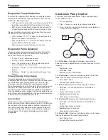
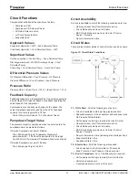
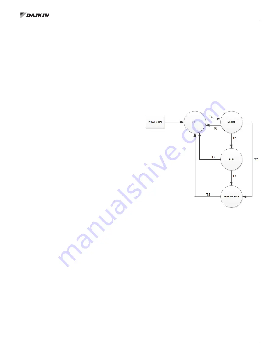
Circuit States
There are four distinct states of control for the circuit as shown.
Figure 19: Circuit State Transitions
T1 – Off to Start
- All of the following must be true:
• Circuit is available to start per the previous section
• Adequate pressure in the evaporator and condenser (see
No Pressure At Start Alarm)
• Unit capacity control logic requires the circuit to start
• No manual reset circuit fault alarms are active
• Circuit Mode set point is set to Enable
• BAS Circuit Mode set point is set to Auto if Control
Source = Network
• No cycle timers are active (including max starts per hour)
• Evaporator State = Run
• Condenser State = Run
T2 – Start to Run
- All of the following are required:
• Circuit has been in the Start state for 20 seconds
•
Evap Pressure ≥ Low Pressure Unload set point
T3 – Run to Pumpdown
- Any of the following are required:
• Unit capacity control logic requires this circuit to stop
• Unit state is pumpdown
• A pumpdown alarm occurs on the circuit
Summary of Contents for Navigator WWV
Page 4: ......


