


I
nsTallaTIon
- K
noCKdown
www.DaikinApplied.com 17
IOM 1264-1 • NAVIGATOR
®
MODEL WWV CHILLERS
Type A Knockdown Disassembly
Removal of specific components only may be necessary for job
site installation. Steps outlined below illustrate knockdown of
compressor, all refrigerant lines and electrical items. Additional
knockdown details will be shipped with the unit in the control
panel. During disassembly, save gaskets for block offs and
bolts, washers, and nuts for use later to install block off plates.
CAUTION
Standard torque specs must be followed when re-installing
bolts, unless otherwise stated for specific components.
Contact Daikin Applied service for this information.
1. Recover refrigerant charge from the unit.
2. Remove discharge line at compressor and condenser
connections.
3. Remove liquid line at evaporator and condenser
connections, leaving the liquid line clamp on the top of
the condenser.
4. Remove jet pump line at shutoff valve on condneser
and evaporator. Reassemble the clamp attached to
the compressor bracket after copper jet pump line is
removed.
5. Remove oil line at Rotolock connection on compressor
and condenser connection. Remove support bracket
attached to compressor mounting foot. Leave the clamp
and bracket attached to the oil line.
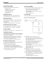
6. Remove power wire harness assemblies from the bottom
of the VFD to the unit control box and to compressor
terminal box but leave the bus bars, electrical barrier,
ground strap, and fittings installed.
Figure 14: Power Wiring Inside VFD
7. Disconnect the thermister wires from the compressor
terminal box and coil them inside the VFD - do not
disconnect from the VFD terminal block. Unbolt VFD
from mounting brackets and use lifting lugs to remove
the panel.
8. Disconnect the high pressure switch from the control box
end only and leave connected to the compressor.
9. Remove compressor using lifting lugs and install
blockoffs on the discharge and suction connections; then
remove suction line.
10. Disconnect all solenoids from the chiller but leave
connected to the control box; the jet pump solenoid
harness should include the solenoid coil.
11. Disconnect the multi-cable connectors from the back
side of the control box. Leave all transducers and flow
sensors installed on the chiller, just remove the cables.
Unmount the control box and use lifting lugs to remove.
the control panel.
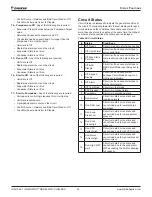
12. Ensure vessel blockoffs are installed at suction,
discharge, and liquid connections as shown in
Figure
15
. Refer to detailed knockdown instructions included
in the chiller control panel for discharge line bolt torque
specifications.
13. Vessels can be further separated at tubesheet braces if
needed, leaving relief valves attached. Use lifting holes
in the tubesheets to properly move vessels.
Figure 15: Vessel Blockoff Locations
Summary of Contents for Navigator WWV
Page 4: ......


