15
|
Piping installation
Installer and user reference guide
99
LREN8~12A7 + LRNUN5A7
CO₂ ZEAS outdoor unit and capacity up unit
4P704142-1 – 2022.08
2
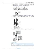
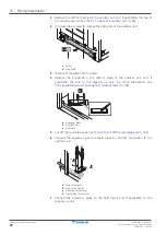
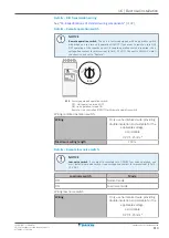
Afterwards, vacuum dry the unit to –100.7 kPaG (-1.007 bar gauge) or less for
at least 1 hour.
3
Repeat vacuum destruction and vacuum drying if the pressure does not reach
–100.7 kPaG (-1.007 bar gauge) or less.
4
Leave the unit for more than 1 hour with a vacuum pressure of –100.7 kPaG
(-1.007 bar gauge) or less. On the vacuum gauge, check if the pressure does
not increase.
15.5 Insulating the refrigerant piping
After finishing the leak test and vacuum drying, the piping must be insulated. Take
into account the following points:
▪
Be sure to insulate the liquid and gas piping (for all units).
▪
For liquid and gas piping: Use heat resistant polyethylene foam which can
withstand a temperature of 70°C.
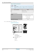
Insulation thickness
Take the following into account when determining the insulation thickness:
Piping
Minimum temperature during
operation
Liquid piping
0°C
Gas piping
–40°C
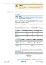
Depending on your local weather conditions, you may need to increase the
thickness of the insulation. If the ambient temperature exceeds 30°C and the
humidity exceeds 80%.
▪
Increase the thickness of the liquid piping with ≥5 mm
▪
Increase the thickness of the gas piping with ≥20 mm
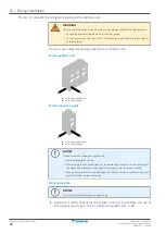
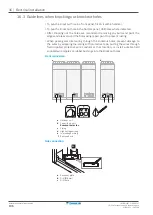
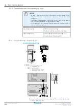
Insulation sealing
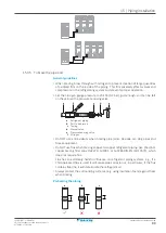
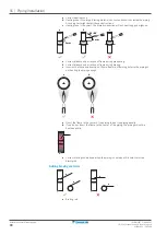
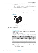
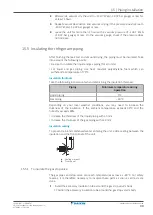
To prevent rain and condensed water entering the unit, add a sealing between the
insulation and the front panel of the unit.
a
a
a
a
b
b
a
Sealing material
b
Front panel
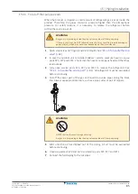
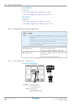
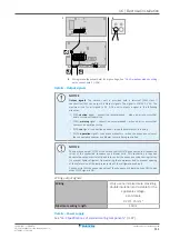
15.5.1 To insulate the gas stop valve
The gas pipes and stop valve can reach temperatures as low as –40°C. For safety
reasons, it is therefore necessary to insulate these parts as soon as all tests are
done.
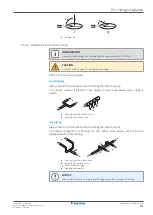
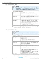
1
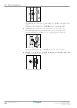
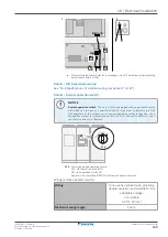
Install the accessory insulation tube around the gas stop valve's body.
▪
Position the accessory insulation tube around the gas stop valve's body.

