15
|
Piping installation
Installer and user reference guide
77
LREN8~12A7 + LRNUN5A7
CO₂ ZEAS outdoor unit and capacity up unit
4P704142-1 – 2022.08
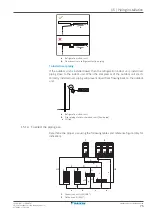
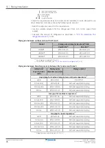
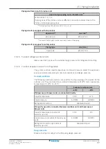
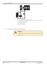
Piping size from branch to indoor unit
Liquid and gas piping: outer diameter size
(a)
Same size as C, D, c, d.
If piping sizes of the indoor units are different, connect a reducer close to the
indoor unit to align piping sizes.
(a)
Piping from branch to indoor unit (C, D, E; c; d; e)
Piping size of spun pipes with stop valves
Liquid side
(a)
Gas side
(a)
Ø15.9×t2.0
Ø22.2×t2.1
(a)
Reducers (field supply) may be required to connect the piping.
Piping size of spun pipes for safety valves
Piping type
Size (mm)
Liquid side
Ø19.1×t2.0
15.1.5 To select refrigerant branch kits
Always use K65 T-joints with a suitable design pressure for refrigerant branching.
15.1.6 To select expansion valves for refrigeration
The system controls liquid temperature and liquid pressure. Select the expansion
valves as indicated according to nominal conditions and design pressure.
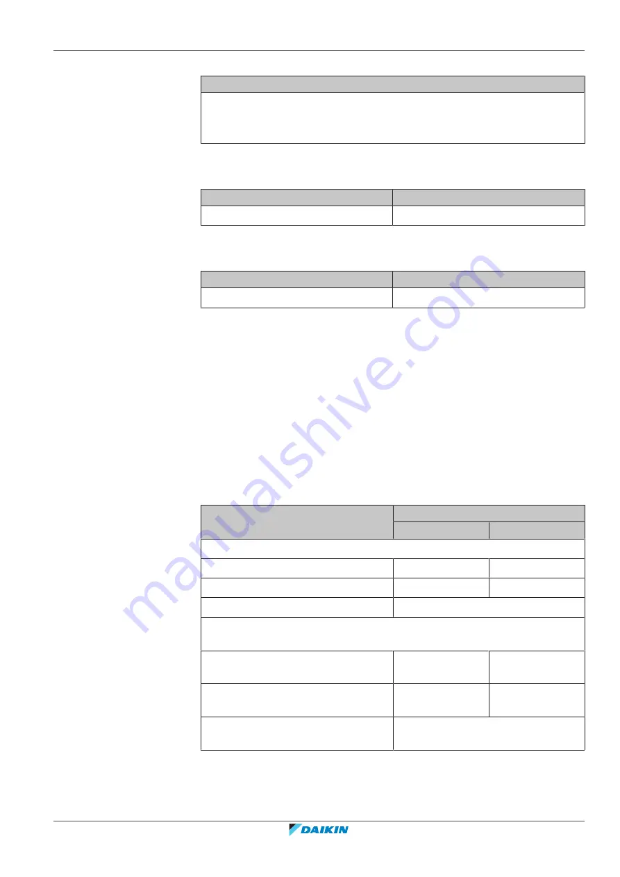
Nominal conditions
The following nominal conditions are valid for the liquid piping at the outlet of the
outdoor unit. They are based on an ambient temperature of 32°C and an evaporate
temperature of –10°C or –35°C.
Evaporate temperature
–10°C
–35°C
If showcases or blower coils are connected directly
Liquid temperature
25°C
12°C
Liquid pressure
6.8 MPa
6.8 MPa
Refrigerant condition
Subcooled liquid
If capacity up unit is connected between outdoor unit and showcases or
blower coils
Liquid temperature (at outlet of
capacity up unit)
15°C
4°C
Liquid pressure (at outlet of capacity up
unit)
6.8 MPa
6.8 MPa
Refrigerant condition (at outlet of
capacity up unit)
Subcooled liquid
Design pressure
Make sure all parts comply to the following design pressure:

