


4
1. The ends of the refrigerant lines must be cut square, de-
burred, cleaned, and be round and free from nicks or dents.
Any other condition increases the chance of a refrigerant
leak.
2. This unit is factory shipped with a holding charge. “Sweep”
the refrigerant line with nitrogen or inert gas during brazing
to prevent the formation of copper-oxide inside the refriger-
ant lines.
3. After brazing, quench the joints with water or a wet cloth to
prevent overheating of the service valve.
4. Ensure the filter drier paint finish is intact after brazing. If
the paint of the steel filter drier has been burned or chipped,
repaint or treat with a rust preventative. This is especially
important on suction line filter driers which are continually
wet when the unit is operating.
NOTE: Be careful not to kink or dent refrigerant lines. Kinked or
dented lines will cause poor performance or compressor damage.
Do NOT make final refrigerant line connection until plugs are
removed from refrigerant tubing.
NOTE: Before brazing, verify indoor piston size by checking the
piston kit chart packaged with indoor unit.
Leak Testing (Nitrogen or Nitrogen-Traced)
To avoid the risk of fire or explosion, never use oxygen, high
pressure air or flammable gases for leak testing of a refrigeration
system.
Pressure test the system using dry nitrogen and soapy water to
locate leaks. If you wish to use a leak detector, charge the system
to 10 psi using the appropriate refrigerant then use nitrogen to
finish charging the system to working pressure then apply the
detector to suspect areas. If leaks are found, repair them. After
repair, repeat the pressure test. If no leaks exist, proceed to sys-
tem evacuation.
System Evacuation
Condensing unit liquid and suction valves are closed to contain
the charge within the unit. The unit is shipped with the valve
stems closed and caps installed. Do not open valves until the
system is evacuated.
1. Connect the vacuum pump with 250 micron capability to the
service valves.
2. Evacuate the system to 250 microns or less using suction
and liquid service valves. Using both valves is necessary as
some compressors create a mechanical seal separating the
sides of the system.
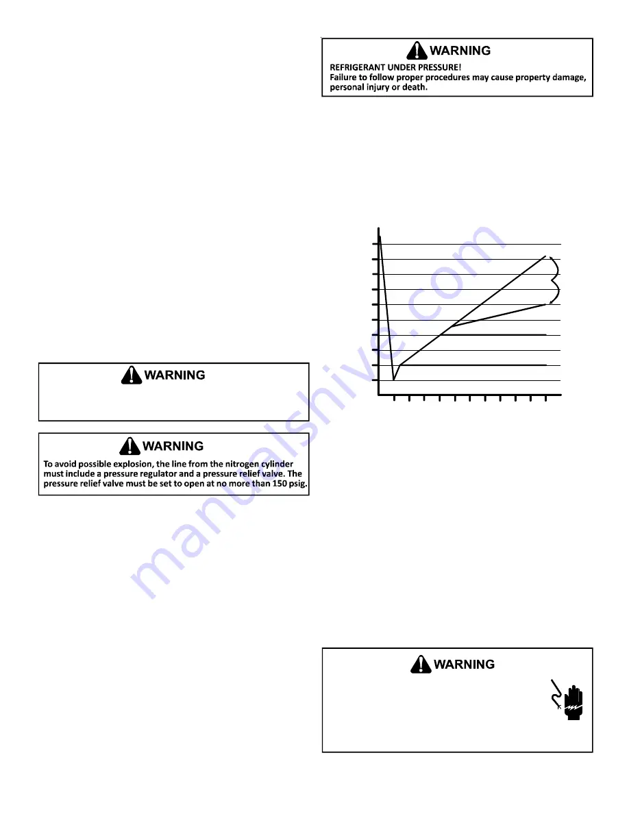
3. Close pump valve and hold vacuum for 10 minutes. Typi-
cally pressure will rise during this period.
5000
4500
4000
3500
3000
2500
2000
1500
1000
500
0 1 2 3 4 5 6 7 8 9
10
LEAK(S)
PRESENT
MINUTES
V
AC
U
U
M
IN
M
IC
RON
S
CONDENSIBLES OR SMALL
LEAK PRESENT
NO LEAKS
NO CONDENSIBLES
•
If the pressure rises to 1000 microns or less and remains
steady the system is considered leak-free; proceed to startup.
• If pressure rises above 1000 microns but holds steady be-
low 2000 microns, moisture and/or noncondensibles may
be present or the system may have a small leak. Return to
step 2: If the same result is encountered check for leaks as
previously indicated and repair as necessary then repeat
evacuation.
•
If pressure rises above 2000 microns, a leak is present. Check
for leaks as previously indicated and repair as necessary
then repeat evacuation.
Refer to the Remote Condensing Unit Service Manual for more
detailed instructions on system evacuation, preliminary charge
adjustment, and final charge adjustment.
Electrical Connections
HIGH VOLTAGE!
Disconnect ALL power before servicing.
Multiple power sources may be present. Failure to do
so may cause property damage, personal injury or
death due to electric shock. Wiring must conform with
NEC or CEC and all local codes. Undersized wires could cause
poor equipment performance, equipment damage or fire.


