background image

13

(2) Check the unit is horizontally level.

NOTE

• The indoor unit is equipped with a built-in drain pump 

and float switch. At each of the unit’s 4 corners, verify 
that it is level by using a level or a water-filled vinyl tube. 
(If the unit is inclined against condensate flow, the float 
switch may malfunction and cause water to drip.)

(3) Tighten the upper nut.
(4) Fix the paper pattern for installation.

• The paper pattern for installation corresponds with the 

measurements of the ceiling opening. Consult the builder 
for details.

• Attach the paper pattern for installation to the unit with the 

screws as shown in the drawing.
The paper pattern for installation is marked for 3 types of ceil-
ing openings. Read the notations carefully when installing.

6. REFRIGERANT PIPING WORK

6-1

GENERAL INSTRUCTIONS

• For refrigerant piping of outdoor units, see the installation man-

ual attached to the outdoor unit.

• Before refrigerant piping work, check which type of refriger-

ant is used. Proper operation is not possible if the types of 
refrigerant are not the same.

• The outdoor unit is charged with refrigerant.

NOTE

• Use a pipe cutter and flare suitable for the type of refrigerant.
• To prevent dust, moisuture or other foreign matter from infil-

trating the tube, either pinch the end or cover it with tape.

• Do not allow anything other than the designated refrigerant 

to get mixed into the refrigerant circuit, such as air, etc. If any 
refrigerant gas leaks while working on the unit, ventilate the 
room thoroughly right away.

6-2

Connecting the refrigerant piping

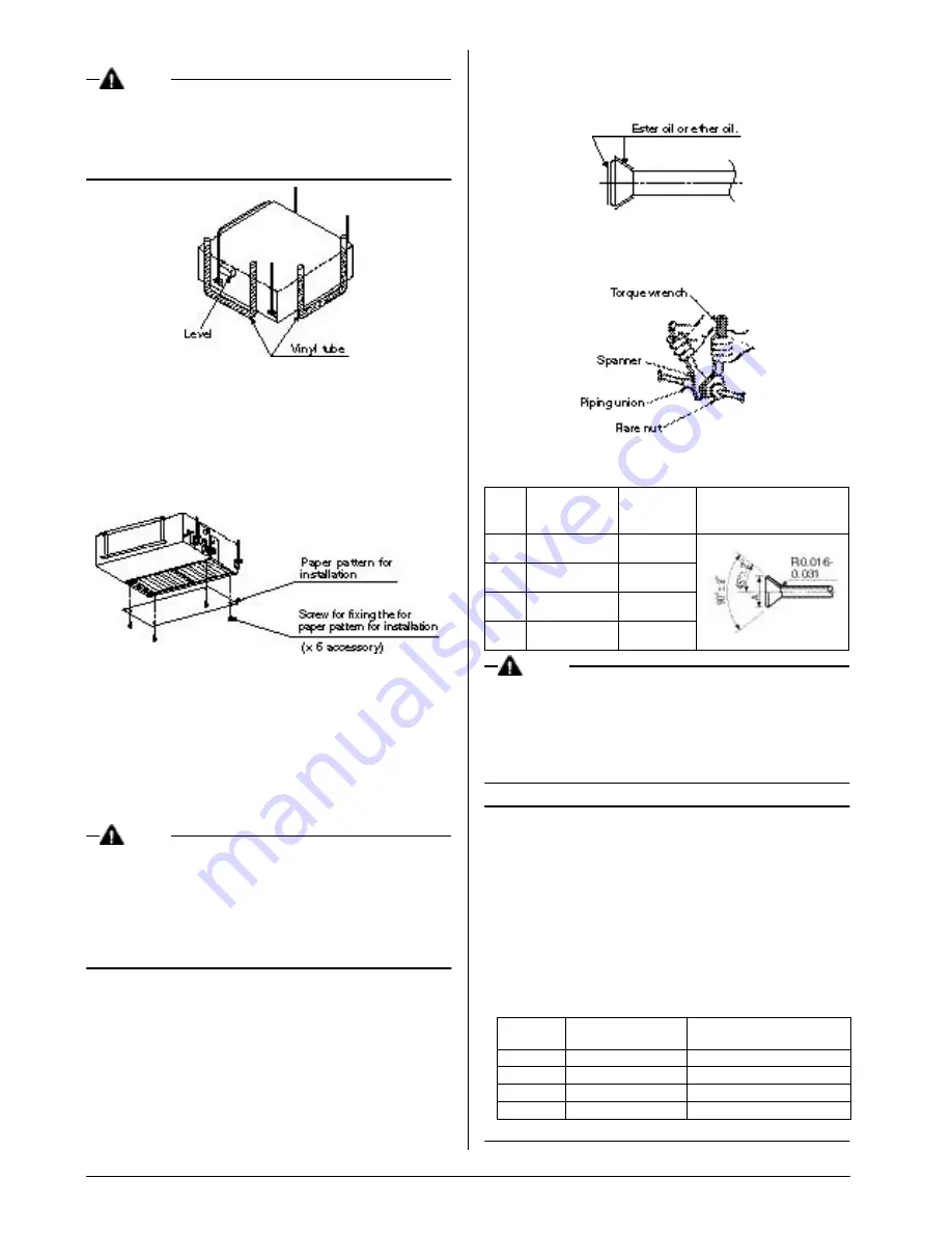
• When connecting the flare nut, coat the flare both inside and 

outside with ester

 oil

 or 

ether

 oil and initially tighten by hand 3 

or 4 turns before tightening firmly.

• To prevent flare nut cracking and gas leaks, be sure to use 

both a spanner and torque wrench together, as shown in the 
drawing below, when connecting or disconnecting pipes to/
from the unit.

• Refer to the Table 3 for the dimensions of flare nut spaces.
• Refer to the Table 3 to determine the proper tightening torque. 

Table 3

NOTE

• Apply ester oil or ether oil around the flare portions before 

connecting.

• The flare nuts used must be those included with the main 

body.

• Over-tightening may damage the flare and cause a refriger-

ant leakage.

Not recommendable but in case of emergency

You must use a torque wrench but if you are obliged to 
install the unit without a torque wrench, you may
follow the installation method mentioned below.

After the work is finished, make sure to check that 
there is no gas leak.

When you keep on tightening the flare nut with a spanner, 
there is a point where the tightening torque 
suddenly increases. From that position, further tighten the 
flare nut the angle shown below:

Table 4

Pipe 

size

Tightening torque

(ft.lbf)

Flare 

dimensions

A (in.)

Flare shape (in.)

 φ

 1/4”

10.4 – 12.7

0.342-0.358

 φ

 3/8”

24.1 – 29.4

0.504-0.520

 φ

 1/2”

36.5 – 44.5

0.638-0.654

 φ

 5/8”

45.6 – 55.6

0.760-0.776

Pipe size

Further tightening 

angle

Recommended arm length of 

tool (in.)

φ 

1/4”

60 to 90 degrees

Approx. 5 7/8

φ 

3/8”

60 to 90 degrees

Approx. 7 7/8

φ 

1/2”

30 to 60 degrees

Approx. 9 13/16

φ 

5/8”

30 to 60 degrees

Approx. 11 13/16

Summary of Contents for FXMQ30MVJU

Page 1: ...in type FXSQ12MVJU FXSQ30MVJU FXSQ18MVJU FXSQ36MVJU FXSQ24MVJU FXSQ48MVJU SYSTEM Inverter Air Conditioners INSTALLATION MANUAL Read these instructions carefully before installation Keep this manual in...

Page 2: ...RK 6 DRAIN PIPING WORK 7 ELECTRIC WIRING WORK 7 WIRING EXAMPLE AND HOW TO SET THE REMOTE CON TROLLER 8 SELECTING INSTALLATION SITE 11 PREPARATIONS BEFORE INSTALLATION 11 INDOOR UNIT INSTALLATION 12 RE...

Page 3: ...of refrig erant leakage Contact the place of purchase for more information Excessive refrigerant in a closed ambient can lead to oxygen deficiency Be sure to use only the specified accessories and pa...

Page 4: ...rts should be done in accordance with the relevant local and national regulations 2 BEFORE INSTALLATION When moving the unit while removing it from the carton box be sure to lift it by holding on to t...

Page 5: ...or and outdoor units power supply wiring and connecting wires at least 3 5ft away from televisions or radios in order to prevent image interference or noise Depending on the radio waves a distance of...

Page 6: ...e strong enough to bear the equipment s weight Use embedded inserts or anchor bolts with new buildings and hole in anchors with old buildings 5 INDOOR UNIT INSTALLATION Installing optional accessories...

Page 7: ...he installation method mentioned below After the work is finished make sure to check that there is no gas leak When you keep on tightening the flare nut with a spanner there is a point where the tight...

Page 8: ...n the unit is running so be sure to provide condensate trap on the condensate outlet See the figure In order to prevent foreign matter from building up inside the piping you should avoid curves as muc...

Page 9: ...rmly When attaching the electric parts box lid make sure no wires get caught in the edges Pass wiring through the wiring through holes to prevent damage to them Make sure the remote controller wiring...

Page 10: ...he INSTALLATION MANUAL OF REMOTE CONTROLLER attached to the remote controller 6 Never connect power supply wiring to the terminal block for remote controller wiring A mistake of the sort could damage...

Page 11: ...SAJ25K36 FXSQ18MVJU 16 3 4 or more BYBS45DJW1 Installation not required 13 3 4 or more KSAJ25K56 FXSQ24MVJU 16 3 4 or more BYBS71DJW1 Installation not required 13 3 4 or more KSAJ25K80 FXSQ30 36 48MVJ...

Page 12: ...res at least 3 5 ft away from televisions or radios in order to prevent image interference or noise Depending on the radio waves a distance of 3 5 ft may not be sufficient enough to eliminate the nois...

Page 13: ...force the ceiling to bearing the weight of the unit 5 INDOOR UNIT INSTALLATION Installing optional accessories except for the decoration panel before installing the indoor unit is easier As for the pa...

Page 14: ...he unit ventilate the room thoroughly right away 6 2 Connecting the refrigerant piping When connecting the flare nut coat the flare both inside and outside with ester oil or ether oil and initially ti...

Page 15: ...flared or a flanged connection Nitrogen should be set to 2 9psi with a pressure reducing valve if brazing while inserting nitrogen into the piping NOTE Do not use flux when brazing refrigerant piping...

Page 16: ...e unit Press to go back to the first mode You can check whether drainage is satisfactory or not by removing the access opening lid and checking the water level of the drain pan through the access open...

Page 17: ...remote controller is as follows 1 Outdoor unit Indoor unit Max 3280 ft Total wiring length 6560 ft 2 Indoor unit Remote controller Max 1640 ft 2 Insulated thickness 1 16 or more Model Power supply wi...

Page 18: ...pply terminal Looseness in the connection may cause overheating Use the specified electric wire Connect the wire securely to the terminal Lock the wire down without applying excessive force to the ter...

Page 19: ...CONNECTOR According to the system static pressure requirement reposi tion the adaptors of PC board inside the electric parts box as shown in the below drawings NOTE The unit is factory set for standar...

Page 20: ...CONTROL BY 2 REMOTE CONTROLLERS Con trolling 1 indoor unit by 2 remote controllers When using 2 remote controllers one must be set to MAIN and the other to SUB MAIN SUB CHANGEOVER 1 Insert a screw dr...

Page 21: ...ORCED OFF at factory set 11 TEST OPERATION Refer to the installation manual of the outdoor unit The operation lamp of the remote controller will flash when an malfunction occurs Check the malfunction...

Page 22: ...0403 HT 3P086156 9N EM03A042B Daikin US Corporation 375 Park Avenue Suite 3308 New York NY 10152 www daikinac com info daikinac com...

Reviews: