


6
(4) Tighten the upper nut.
6.
REFRIGERANT PIPING WORK
〈
For refrigerant piping of outdoor units, see the installation
manual attached to the outdoor unit.
〉
〈
Execute heat insulation work completely on both sides of
the gas piping and the liquid piping. Otherwise, a water
leakage can result sometimes.
Use insulation that can withstand temperatures of at least
250°F. Reinforce the insulation on the refrigerant piping
according to the installation environment. If the temperature
above the ceiling might reach 86°F or the humidity RH80%.
Condensation may form on the surface of the insulation.
〉
CAUTION
Follow the points at below.
• Use a pipe cutter and flare suitable for the type of refrigerant.
• Apply ester oil or ether oil to the flare section when using a
flare connection.
• Only use the flare nuts included with the unit. Using different
flare nuts may cause the refrigerant to leak.
• To prevent dust, moisture or other foreign matter from infil-
trating the piping, either pinch the end or cover it with tape.
• Do not allow anything other than the designated refrigerant to
get mixed into the refrigerant circuit, such as air, etc. If any
refrigerant gas leaks while working on the unit, ventilate the
room thoroughly right away.
(1) Connect the piping.
• The outdoor unit is charged with refrigerant.
• Be sure to use both a spanner and torque wrench together,
as shown in the drawing, when connecting or disconnecting
pipes to/from the unit.
(Refer to Fig. 6)
• Refer to the Table 1 for the dimensions of flare nut spaces.
• Apply ester oil or ether oil to flare section (both inside and
out) when using flare nut connections and then turn 3 or 4
times by hand.
(Refer to Fig. 7)
• Refer to Table 1 for tightening torque.
Table 1
CAUTION
Overtightening may damage the flare and cause leaks.
Be careful for oil not to adhere to any portions other than
a flare part. If oil adhere to resin parts etc., there is a pos-
sibility of damaging by deterioration.
• Refer to Table 2 if no torque wrench is available.
Using a wrench to tighten flare nuts causes the tightening
torque to suddenly grow much tighter after a certain point.
From there, tighten the nut further by the appropriate angle
listed in Table 2.
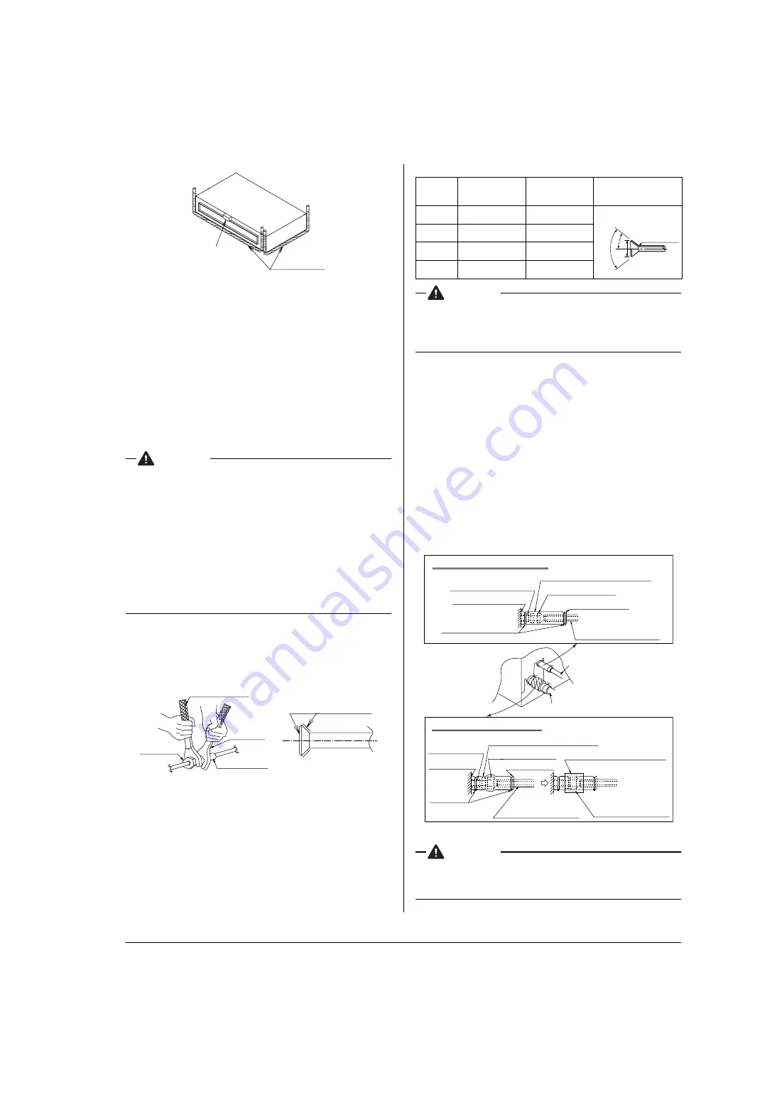
(2) After the work is finished, make sure to check that
there is no gas leak.
(3) After checking for gas leaks, be sure to insulate the
pipe connections referring to Fig. 8.
• Insulate using the insulation for fitting (3) (4) included with
the liquid and gas pipes. Besides, make sure the insula-
tion for fitting (3) (4) on the liquid and gas piping has its
seams facing up.
(Tighten both edges with clamp (9).)
• For the gas piping, wrap the mid. sealing pad (6) over the
insulation for fitting (4) (flare nut part).
CAUTION
Be sure to insulate any field piping all the way to the piping
connection inside the unit. Any exposed piping may cause
condensation or burns if touched.
Vinyl tube
Level
Torque wrench
Spanner
Ester oil or ether oil
Piping union
Flare nut
Fig. 6
Fig. 7
Pipe size
(in.)
Tightening torque
(ft.lbf)
Flare dimensions A
(in.)
Flare shape (in.)
φ
1/4
10.4–12.7
0.342–0.358
φ
3/8
24.1–29.4
0.504–0.520
φ
1/2
36.5–44.5
0.638–0.654
φ
5/8
45.6–55.6
0.760–0.776
R0.016-0.031
A
90˚± 2˚
45˚±2˚
Gas pipe
Piping insulation
material (main unit)
Attach to base
Flare nut connection
Turn seams up
Mid. sealing pad (6) (accessory)
Insulation for fitting (4) (accessory)
Gas Piping Insulation Procedure
Liquid Piping Insulation Procedure
(accessory)
Clamp (9)
Piping insulation material
(Field supply)
Clamp (9) (accessory)
Flare nut connection
Turn seams up
Piping insulation material
(Field supply)
Piping insulation material
(main unit)
Attach to base
Main unit
Fig. 8
Liquid pipe
Insulation for fitting (3) (accessory)
Wrap over the top of
the flare nut connection.
Main unit


