background image

11

Refer to Table 1 for tightening torque.

Table 1

Not recommendable but in case of emergency

You must use a torque wrench but if you are obliged to install the unit without a torque wrench, you may
follow the installation method mentioned below.

After the work is finished, make sure to check that there is no gas leak.

When you keep on tightening the flare nut with a spanner, there is a point where the tightening torque 
suddenly increases. From that position, further tighten the flare nut the angle shown below:
Table 2

CAUTION

CAUTION TO BE TAKEN WHEN BRAZING REFRIGERANT PIPING

“Do not use flux when brazing refrigerant piping. Therefore, use the phosphor copper brazing filter metal 
(BCuP) which does not require flux.”
(Flux has extremely harmful influence on refrigerant piping system. For instance, if the chlorine based flux is 
used, it will cause pipe corrosion or, in particular, if the flux contains fluorine, it will damage the refrigerant oil.)

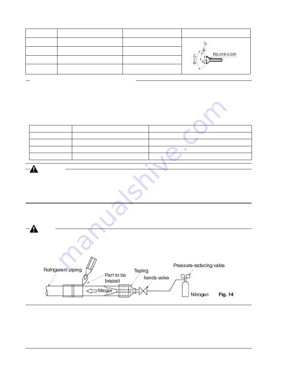
When brazing the refrigerant piping, only begin brazing after having carried out nitrogen substitution 
(NOTE 1) or while inserting nitrogen into the refrigerant piping (NOTE 2). Once this is done, connect the 
indoor unit with a flared or a flanged connection.

NOTE

1.

Refer to the “Manual for Multi Installation for Buildings” for directions on how to carry out nitrogen 
substitution. (Inquire with your dealer.)

2.

Nitrogen should be set to 2.9 psi with a pressure-reducing valve if brazing while inserting nitrogen into the 
piping. 

(Refer to Fig. 14)

After checking for gas leaks, be sure to insulate the pipe connections using the supplementary piping 
insulation tubing and insulating tape (4). The insulating tape (4) should be wrapped from the L-shaped bend 
all the way to the end inside the unit.

 (Refer to Fig. 15)

Pipe size

Tightening torque (ft-lbf)

Flare dimensions A (in.)

Flare shape (in.)

 φ 

1/4”

10.5 – 12.7

0.343 – 0.358

 φ 

3/8”

24.1 – 29.4

0.504 – 0.520

 φ

 1/2”

36.5 – 44.5

0.638 – 0.654

 φ

 5/8”

45.6 – 55.6

0.760 – 0.776

Pipe size (in.)

Further tightening angle

Recommended arm length of tool (in.)

φ

 1/4”

60 to 90 degrees

Approx. 5 7/8”

φ

 3/8”

60 to 90 degrees

Approx. 7 7/8”

φ

 1/2”

30 to 60 degrees

Approx. 9 13/16”

φ

 5/8”

30 to 60 degrees

Approx. 11 13/16”

Summary of Contents for FXAQ12MVJU

Page 1: ...U FXAQ18MVJU FXAQ24MVJU SYSTEM Inverter Air Conditioners Read these instructions carefully before installation Keep this manual in a handy place for future reference This manual should be left with th...

Page 2: ...TALLATION 3 3 SELECTING INSTALLATION SITE 5 4 INDOOR UNIT INSTALLATION 6 5 REFRIGERANT PIPING WORK 10 6 DRAIN PIPING WORK 12 7 ELECTRIC WIRING WORK 13 8 WIRING EXAMPLE AND HOW TO SET THE REMOTE CONTRO...

Page 3: ...CAUTION Indication a potentially hazardous situation which if not avoided may result in minor or moderate injury It may also be sued to alert against unsafe practices NOTE Indication situation that m...

Page 4: ...gers Touching a switch with wet fingers can cause electric shock Install a leak circuit breaker as required If a leak circuit breaker is not installed electric shock may result Do not install the air...

Page 5: ...n site Where unpacking is unavoidable use a sling of soft material or protective plates together with a rope when lifting to avoid dam age or scratches to the unit For the installation of an outdoor u...

Page 6: ...one what is likely to occur Check Are the indoor and outdoor unit fixed firmly The units may drop vibrate or make noise Is the gas leak test finished It may result in insufficient cooling Is the unit...

Page 7: ...g blocks the air passage Where condensate can be properly drained Where the wall is not significantly tilted Where not exposed to flammable gases Where piping between indoor and outdoor units is possi...

Page 8: ...t This may damage the horizontal flaps 1 Open the piping through hole The refrigerant pipe and drain pipe can be passed out in one of 5 directions left bottom left back left bottom right and back righ...

Page 9: ...oncrete use commercially available foundation bolts M8 M10 or equivalent 3 If using the left bottom left or bottom right positions for the piping cut out the through hole for the piping in the front g...

Page 10: ...he screws 2 places in case of 12 type 3 places in case of 18 24 type securing the front grill 3 Remove the tabs 3 places securing the front grill by pushing them in the direction of the arrows 4 Makin...

Page 11: ...ONNECT WIRINGS and remote controller wiring through the wiring guide in through the back of the indoor unit and to the front 8 Connect the piping See 5 REFRIGERANT PIPING WORK and Fig 10 Seal the pipi...

Page 12: ...ant is used Proper operation is not pos sible if the types of refrigerant are not the same NOTE Use a pipe cutter and flare suitable for the type of refrigerant To prevent dust moisture or other forei...

Page 13: ...gerant piping only begin brazing after having carried out nitrogen substitution NOTE 1 or while inserting nitrogen into the refrigerant piping NOTE 2 Once this is done connect the indoor unit with a f...

Page 14: ...t for the points in the figure 16 when performing drain work When extending the drain hose use a commercially available drain extension hose and be sure to insulate the extended section of the drain h...

Page 15: ...units Mark each indoor unit as unit A unit B and be sure the terminal block wiring to the outdoor unit and BS unit is properly matched If wiring and piping between the outdoor unit and indoor unit ar...

Page 16: ...clamp small 5 Refer to Fig 21 Connect the power supply wiring and ground wiring to the power supply terminal block 3P When doing this firmly secure using the included clamp small 5 according to the fi...

Page 17: ...o wirings get caught in the edges Pass wiring through the wiring through holes to prevent damage to them Make sure the remote controller wiring and transmission wire the wiring between the units and o...

Page 18: ...l not be properly tightened If the terminal screws are tightened too hard screws might be damaged Refer to the table below for the tightening torque of the terminal screws 3 Do not connect wires of di...

Page 19: ...wer supply wiring of each unit with a switch and fuse as shown in the drawing COMPLETE SYSTEM EXAMPLE 3 systems 1 When using 1 remote controller for 1 indoor unit Normal operation 2 For group control...

Page 20: ...MAIN SUB CHANGEOVER 1 Insert a screwdriver into the recess between the upper and lower part of remote controller and working from the 2 positions pry off the upper part The remote controller PC board...

Page 21: ...ails refer to the manual of each optional controllers for centralized control 9 FIELD SETTINGS 1 Make sure the service lids are closed on the indoor and outdoor units 2 Field settings must be made fro...

Page 22: ...l display to identify the point of trouble An explanation of malfunction codes and the corresponding trouble is provided in the installation manual of the outdoor unit If any of the items in Table 5 a...

Page 23: ...0407 HT 3PN01417 9V EM04A013 Daikin US Corporation 375 Park Avenue Suite 3308 New York NY 10152 www daikinac com info daikinac com...

Reviews: