background image


FDQ125C7VEB
Split System air conditioners
4PW71105-1 – 08.2011

Installation manual

4

Refer to 

Table 1

 for the dimensions of flare nut spaces and the

appropriate tightening torque. (Overtightening may damage the
flare and cause leaks.)
Table 1 

When connecting the flare nut, coat the flare inner surface with
ether oil or ester oil and initially tighten 3 or 4 turns by hand
before tightening firmly.

If the refrigerant gas leaks during the work, ventilate the area. A
toxic gas is emitted by the refrigerant gas being exposed to a fire.

Make sure there is no refrigerant gas leak. A toxic gas may be
released by the refrigerant gas leaking indoor and being
exposed to flames from an area heater, cooking stove, etc.

Finally, insulate as shown in the figures below.

Piping insulation procedure

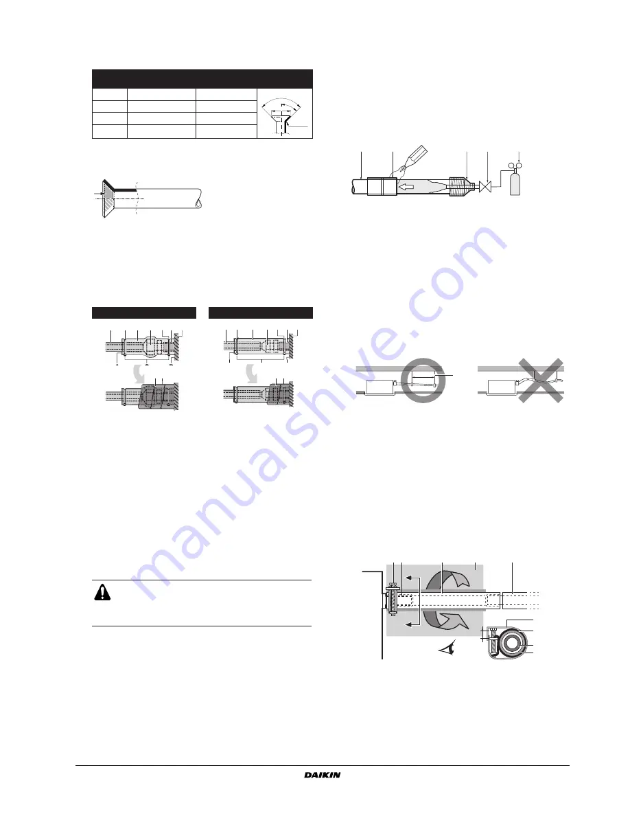
Cautions for brazing

Be sure to carry out a nitrogen blow when brazing.
Brazing without carrying out nitrogen replacement or releasing
nitrogen into the piping will create large quantities of oxidized
film on the inside of the pipes, adversely affecting valves and
compressors in the refrigerating system and preventing normal
operation.

When brazing while inserting nitrogen into the piping, nitrogen
must be set to 0.02 MPa with a pressure-reducing valve (=just
enough so that it can be felt on the skin).

D

RAIN


PIPING


WORK

Rig the drain piping as shown in the figure and take measures
against condensation. Improperly rigged piping could lead to leaks
and eventually wet furniture and belongings.

Install the drain pipes.
-

Keep piping as short as possible and slope it downwards at a 
gradient of at least 1/100 so that air may not remain trapped 
inside the pipe.

-

Keep pipe size equal to or greater than that of the connecting 
pipe (vinyl pipe of 25 mm nominal diameter and 32 mm outer 
diameter).

-

Push the supplied drain hose as far as possible over the 
drain socket.

-

Tighten the metal clamp until the screw head is less than 
4 mm from the metal clamp part as indicated in the 
illustration.

-

Wrap the supplied large sealing pad over the metal clamp 
and drain hose to insulate and fix it with clamps.

Pipe 

gauge

Tightening torque 

(N•m)

Flare dimension 

A (mm)

Flare shape

Ø6.4

15~17

8.7~9.1

Ø9.5

33~39

12.8~13.2

Ø12.7

50~60

16.2~16.6

Ø15.9

63~75

19.3~19.7

Gas piping

Liquid piping

1

Piping insulation material (field supply)

2

Flare nut connection

3

Insulation for fitting (delivered with the unit)

4

Piping insulation material (main unit)

5

Main unit

6

Clamp (field supply)

7

Medium 1 sealing pad for gas piping (delivered with the unit)
Medium 2 sealing pad for liquid piping (delivered with the unit)

A

Turn seams up

B

Attach to base

C

Tighten the part other than the piping insulation material

D

Wrap over from the base of the unit to the top of the flare nut 
connection

For local insulation, be sure to insulate local piping all
the way into the pipe connections inside the unit.

Exposed piping may cause condensation or may
cause burns when touched.

R0.4~0.8

45

° ±

2

90

°±

2

A

A

B

D

C

7

1

2

3

4

5

6

6

A

B

C

1

2

3

4

5

6

6

D

7

1

Refrigerant piping

2

Part to be brazed

3

Taping

4

Hands valve

5

Pressure-reducing valve

6

Nitrogen

1

Hanging bar

1

Drain socket (attached to the unit)

2

Drain hose (supplied with the unit)

3

Metal clamp (supplied with the unit)

4

Drain piping (field supply)

5

Large sealing pad (supplied with the unit)

1

2

3

4

5

6

6

1-1.5 m

1

1

2

3

5

4 mm

3

5

2

A

A'

A'

A-A'

1

4

A

A'

Summary of Contents for FDQ125C7VEB

Page 1: ...INSTALLATION MANUAL FDQ125C7VEB Split System air conditioners ...

Page 2: ... 680 1 5 3 4 2 7 180 460 160 160 300 425 1 3 2 180 460 350 1 2 2 3 5 0 75 625 A 300 mm 1 1 5 m 2 3 1 4 100 mm 1 0 625 mm 1 1 2 4 5 3 6a 7a 7b 7c 6b 6c 8 9 10 11 2 1 3 5 4 700 630 A B 4 3 2 1 1 1 2 4 5 6 2 1 5 4 1 3 2 6 4 4 A A 1 2 3 4 5 6a 6b 6c 7a 7b 7c 8 9 10 11 ...

Page 3: ...ÙÔ ÈÛÙÔ ÔÈËÙÈÎfi C 08 Nota tal como estabelecido em A e com o parecer positivo de B de acordo com o Certificado C 09 Примечание как указано в A и в соответствии с положительным решением B согласно Свидетельству C 10 Bemærk som anført i A og positivt vurderet af B i henhold til Certifikat C 11 Information enligt A och godkänts av B enligt Certifikatet C 12 Merk som det fremkommer i A og gjennom posi...

Page 4: ...east 2 5 m from the floor Where the air contains high levels of salt such as air near the ocean and where voltage fluctuates a lot e g in factories Also in vehicles or vessels Do not install accessories on the casing directly Drilling holes in the casing may damage electrical wires and consequently cause fire Accessories Check if the following accessories are included with your unit Screws for fix...

Page 5: ...e to prevent that the fan blades or heat exchanger be touched The protection must comply with relevant European and national regulations 3 Use suspension bolts for installation Check whether the ceiling is strong enough to support the weight of the indoor unit If there is a risk reinforce the ceiling before installing the unit PREPARATIONS BEFORE INSTALLATION 1 Relation of ceiling opening to unit ...

Page 6: ...e gas piping and the liquid piping Otherwise this can sometimes result in water leakage Before rigging tubes check which type of refrigerant is used Use a pipe cutter and flare suitable for the used refrigerant To prevent dust moisture or other foreign matter from infiltrating the tube either pinch the end or cover it with tape Use copper alloy seamless pipes ISO 1337 The outdoor unit is charged w...

Page 7: ...t of at least 1 100 so that air may not remain trapped inside the pipe Keep pipe size equal to or greater than that of the connecting pipe vinyl pipe of 25 mm nominal diameter and 32 mm outer diameter Push the supplied drain hose as far as possible over the drain socket Tighten the metal clamp until the screw head is less than 4 mm from the metal clamp part as indicated in the illustration Wrap th...

Page 8: ...l board and confirm drain operation Be aware that the fan will turn during the operation After confirming drainage turn off the power 1 Ceiling slab 2 Hanger bracket 3 Adjustable range 4 Drain raising pipe 5 Drain hose supplied with the unit 6 Clamp metal supplied with the unit Installation A mm Rear suction installation 231 When canvas duct is installed 350 530 When air inlet panel is directly in...

Page 9: ... the terminal Use torques according to the table below When attaching the control box lid make sure not to pinch any wires After all wiring connections are done fill in any gaps in the casing wiring holes with putty or insulation material field supply thus to prevent small animals or dirt from entering the unit from outside and causing short circuits in the control box 2 Do not connect wires of di...

Page 10: ... fan operation mode perform the next steps stop the air conditioning unit go to field setting mode select mode No 21 or 11 in case of group setting set the first code No to 7 set the second code No to 03 Return to normal operating mode after setting these settings and press the ON OFF operation button The operation lamp will light up and the air conditioning unit will start the fan operation for a...

Page 11: ...and decoration panel TEST OPERATION Refer to the section of For the following items take special care during construction and check after installation is finished on page 2 After finishing the construction of refrigerant piping drain piping and electric wiring conduct test operation accordingly to protect the unit 1 Open the gas side stop valve 2 Open the liquid side stop valve 3 Electrify crank c...

Page 12: ...DIODE BRIDGE V2R POWER MODULE X1M TERMINAL STRIP POWER SUPPLY X2M TERMINAL STRIP CONTROL Z1C NOISE FILTER FERRITE CORE Z1F NOISE FILTER CONNECTOR OPTIONAL ACCESSORY X28A CONNECTOR POWER SUPPLY FOR WIRING X33A CONNECTOR FOR WIRING X35A CONNECTOR ADAPTOR WIRED REMOTE CONTROLLER R1T THERMISTOR AIR SS1 SELECTOR SWITCH MAIN SUB FIELD WIRING BLK BLACK ORG ORANGE CONNECTOR BLU BLUE PNK PINK WIRE CLAMP BR...

Page 13: ......

Page 14: ......

Page 15: ... 2 3 4 5 P1 P2 6 2 3 4 5 P1 P2 2 3 4 5 P1 P2 P1 P2 1 2 3 1 2 3 1 2 3 4 5 P1 P2 P1 P2 6 13 1 2 3 2 3 1 2 3 4 5 P1 P2 P1 P2 P1 P2 6 6 1 2 L N 3 2 3 2 3 1 2 3 4 5 P1 P2 P1 P2 6 L N L N 1 1 1 1 1 1 L N 1 2 3 L N 1 2 3 1 2 3 L N 1 2 3 1 2 3 L N 1 2 3 12 13 14 15 16 17 ...

Page 16: ...4PW71105 1 08 2011 Copyright 2011 Daikin ...

Reviews: