


D-EIMWC00908-16EN - 21/52
Electrical installation
General specifications
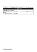
CAUTION
All electrical connections to the machine must be carried out in compliance with laws and regulations in force.
All installation, management and maintenance activities must be carried out by qualified personnel.
Refer to the specific wiring diagram for the machine that you have purchased and which was sent with the unit. Should
the wiring diagram not appear on the machine or should it have been lost, please contact your nearest manufacturer
office, who will send you a copy.
CAUTION
Only use copper conductors. Failure to use copper conductors could result in overheating or corrosion at connection
points and could damage the unit.
To avoid interference, all control wires must be installed separately from the power cables. Use separate electrical
conduits for this purpose.
CAUTION
Before any installation and connection work, the system must be switched off and secured.
The presence of capacitors within the VFD ensures there is voltage downstream of the inverters, even if the
disconnecting switch is open, for several minutes. After switching off the unit, the intermediate circuit capacitors of the
inverter are still charged with high voltage for a short period of time. The unit can be worked on again after it has been
switched of for 10 minutes. Please consult the compressor manual for further details.
CAUTION
The units of the series are provided with non-linear high power electrical components (compressor VFD, which introduce
higher harmonics) can cause considerable dispersion to earth, of about 2 A.
The electricity supply system protection must take the above values into account.
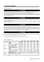
Table 2 - Electrical data
320FZ
430FZ
520FZ
640FZ
860FZ
C10FZ
Power Supply
Phase
---
3
3
3
3
3
3
Frequency
Hz
50
50
50
50
50
50
Voltage
V
400
400
400
400
400
400
Voltage Tolerance
Minimum
%
-10%
-10%
-10%
-10%
-10%
-10%
Maximum
%
+10%
+10%
+10%
+10%
+10%
+10%
Unit
Maximum starting current
A
135
231
176
270
420
352
Nominal running current
(1)
A
104
142
168
207
285
335
Maximum running current
(2)
A
135
210
176
270
420
352
Maximum current for wires sizing
A
149
231
194
297
462
385
Compressor
Phase
No.
3
3
3
3
3
3
Voltage
V
400
400
400
400
400
400
Voltage Tolerance
Minimum
%
-10%
-10%
-10%
-10%
-10%
-10%
Maximum
%
+10%
+10%
+10%
+10%
+10%
+10%
Maximum running current
(2)
A
135
210
176
135+135
210+210
176+176
Starting method
---
VFD
Notes (1)
Unit absorbed current at the following nominal conditions: evaporator water temperature 12/7°C; condenser water temperature 30/35°C, unit at full load
operation with maximum capacity
Notes (2)
Unit maximum absorbed current regardless operating conditions
Summary of Contents for EWWD320
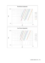
Page 16: ...D EIMWC00908 16EN 16 52 Figure 4 Evaporator pressure drop...
Page 17: ...D EIMWC00908 16EN 17 52...
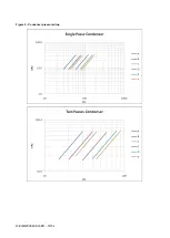
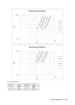
Page 18: ...D EIMWC00908 16EN 18 52 Figure 5 Condenser pressure drop...
Page 34: ...D EIMWC00908 16EN 34 52 Figure 12 Compressor overview...
Page 50: ...D EIMWC00908 16EN 50 52...
Page 51: ...D EIMWC00908 16EN 51 52...


