D-EIMWC00908-16EN - 8/52
Technical Specifications
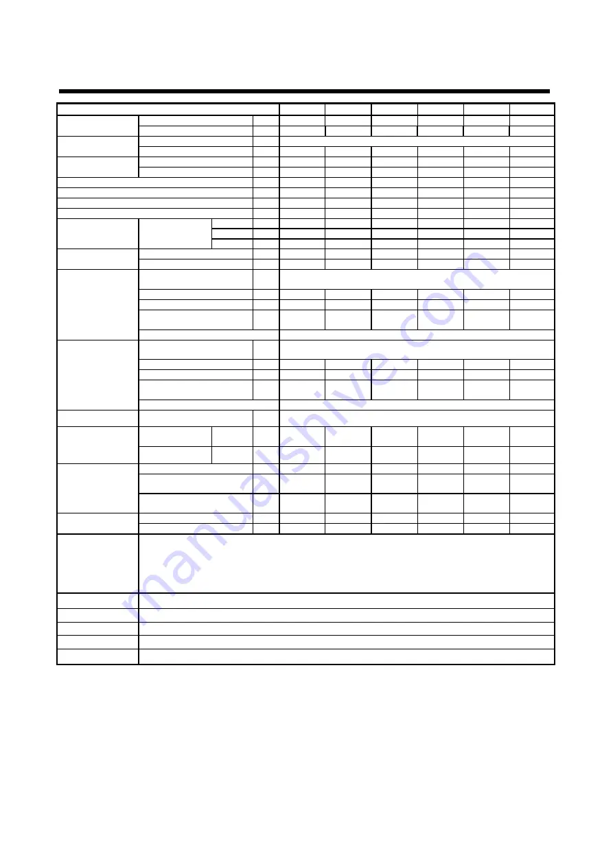
EWWD
320FZ
430FZ
520FZ
640FZ
660FZ
C10FZ
Cooling Capacity
(1)
Min
(2)
kW
114
128
172
114
128
172
Max
kW
317
429
521
635
856
1048
Capacity control
Type
---
Variable speed centrifugal compressor
Minimum capacity
(1)
%
36
30
33
18
15
16
Unit power input
(1)
At min capacity
kW
21.6
27.7
33.1
21.6
27.7
33.1
At max capacity
kW
65.9
85.7
104.2
132.3
171.1
205.5
EER
(1)
At min capacity
---
5.3
4.6
5.2
5.3
4.6
5.2
At max capacity
---
4.8
5.0
5.0
4.8
5.0
5.0
ESEER
(3)
8.4
8.6
9.2
8.6
8.5
9.3
IPLV
(3)
---
8.9
9.2
9.7
9.4
9.2
9.9
Dimensions
Unit
Height
mm
1823
1823
1823
1755
1748
1794
Width
mm
1276
1276
1276
1790
1853
1904
Length
mm
3254
3254
3419
3441
3289
3401
Weight
Unit
kg
2360
2416
2546
3709
4095
4765
Operating Weight
kg
2520
2634
2812
4074
4548
5330
Evaporator
Type
---
Flooded Shell&Tube
– Two water passes in standard conditions
(1 to 4 water passes available as option)
Water volume
l
Nominal water flow rate
(4)
l/s
15.1
20.5
24.9
30.3
40.9
50.1
Nominal Water pressure
drop
(4)
kPa
30.1
30.5
23.3
18.3
20.9
11.3
Insulation material
Closed cell
Condenser
Type
---
Flooded Shell&Tube
– Two water passes in standard conditions
(1 to 4 water passes available as option)
Water volume
l
Nominal water flow rate
(4)
l/s
18.3
24.6
29.9
36.7
49.1
59.9
Nominal Water pressure
drop
(4)
kPa
24.3
24.5
28.2
23.7
25.3
29.3
Insulation material
None (available as an option)
Compressor
Type
---
Frictioneless Centrifugal Compressor Oil free
Sound level
Sound
Power
Cooling
dB(A)
89,0
90,1
91,2
92,4
93,6
94.6
Sound Pressure
(5)
Cooling
dB(A)
70,9
72,0
73,0
73,8
75,1
75,9
Refrigerant circuit
Refrigerant type
---
R-134a
R-134a
R-134a
R-134a
R-134a
R-134a
Refrigerant
charge
kg.
210
190
180
220
300
300
N. of
circuits
No.
1
1
1
1
1
1
Piping connections
Evaporator water inlet/outlet
mm
168.3
168.3
219.1
219.1
219.1
273.0
Condenser water inlet/outlet
mm
168.3
168.3
168.3
219.1
219.1
219.1
Safety devices
Compressors integrate safety functions such as:
-
Low Suction and High Discharge Pressure
-
SurgeHigh Motor Temperature
-
Low Motor Current
-
Starter Fault
-
Sensor Fault
-
Evaporator
– Condenser Water Flow Loss
Notes (1)
Minimu and maximum capacity, unit power input EER are based on the following nominal conditions: evaporator water temperature 12/7°C;
condenser water temperature 30/35°C, unit at full load operation.
Notes (2)
For two compressors unit minimum capacity is with one compressor only runnin
Notes (3)
ESEER and IPLV are calculated with 100% load equal to maximum capacity
Notes (4)
Nominal flow rate an pressure drop are at maximum capacity with two passes heat exchangers
Notes (5)
The values are according to ISO 3744 and are referred to: evaporator water temperature 12/7°C; condenser water temperature 30/35°C, unit at full
load operation at maximum capacity
Summary of Contents for EWWD320
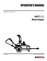
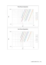
Page 16: ...D EIMWC00908 16EN 16 52 Figure 4 Evaporator pressure drop...
Page 17: ...D EIMWC00908 16EN 17 52...
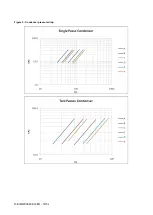
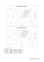
Page 18: ...D EIMWC00908 16EN 18 52 Figure 5 Condenser pressure drop...
Page 34: ...D EIMWC00908 16EN 34 52 Figure 12 Compressor overview...
Page 50: ...D EIMWC00908 16EN 50 52...
Page 51: ...D EIMWC00908 16EN 51 52...