D - KIMAC00512-09EN - 29/40
the request of cooling load and the capacity is depending from the number of the compressors running and the
unloading position of them.
To run the unit in heat recovery mode follow the items listed below:
1) Verify the installation of the water flow switch done by the installer and check the electrical connection at
M3.426 and M3.427 terminal blocks inside the electrical panel
2) Verify the installation of the microprocessor sensor in the pocket well of the water return common header
(done by the installer)
3) Check the set point of the return water temperature on the display of the microprocessor “TC10” (Carel IR32).
Do not exceed the max water temperature allowed (see the operating limits) to avoid the shut-down the unit
for high pressure.
4) Switch the water pump on
5) Switch “ON” the selector “Q7” that allow the unit to run in heat recovery mode. If the microprocessor TC10 is
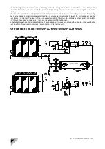
asking for hot water, the 4 ways-valve change the refrigerant circuit from the condenser coil to the heat
recovery condenser (first step) and insert the other circuits until the return hot water is matching the set point.
In that condition the fan motors of the respective condenser coil are switched “OFF”. Vice-versa, when the
microprocessor is reducing the steps, the 4 ways-valve change the refrigerant circuit from the heat recovery
condenser to the condenser coil and switching on the respective fan motors.
6) In case of lack of water in the heat recovery condenser the unit is automatically switched on cooling mode
only.
Standard controls
High pressure control
The high pressure switch will shut-down the compressor when the discharge pressure exceeds the setting point
value.
Phase/voltage monitor
The phase/voltage monitor is a device which provides protection against three-phase electrical motor loss due to
power failure conditions, phase loss, and phase reversal. Whenever any of these conditions occur, a contact
opens to the microprocessor which then de-energizes all inputs. When proper power is restored, contacts close
and microprocessor enables compressors for operation. When three-phase power has been applied, the output
relay should close and the "run light" should come on. If the output relay does not close, perform the following
tests:
1. Check the voltages between L1-L2, L1-L3 and L2-L3 (L1, L2, L3 are the three phases). These voltages should
be approximately equal and 10% of the rated three-phase line-to-line voltage.
2. If these voltages are extremely low or widely unbalanced check the power system to determine the cause of the
problem.
3. If the voltages are good, using a phase tester, verify that phases are in A, B, C sequence for L1, L2 and L3.
Correct rotation is required for compressor operation. If required to do so by phase sequence, turn off the power
and interchange any two of the supply power leads at the disconnect main switch. This may be necessary as the
phase voltage monitor is sensitive to phase reversal. Turn on the power. The output relay should now close after
the appropriate delay.
Summary of Contents for EWAP 800-C18AJYNN
Page 1: ...D KIMAC00512 09EN 1 40 ...


