ESIE10-01
General Outline
1–45
3
1
4
5
1.17
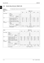
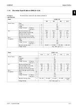
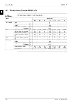
Electrical Specifications: EWAD~C-XS
Electrical
specifications
The table below contains the electrical specifications
Model
EWAD~C-XS
760
830
890
990
Power Supply
Phase
3
Frequency
Hz
50
Voltage
V
400
Voltage Tolerance
Minimum
%
-10%
Maximum
%
+10%
Unit
Maximum
starting
current
A
636.4 681.2 681.2 920.2
Nominal running current cooling
A
386
423
463
511
Maximum
running
current
A
494 548 594 659
Maximum current for wires sizing
A
543
603
653
725
Fans
Nominal running current in cooling
A
48
56
56
64
Compressor
Phase
No.
3
Voltage
V
400
Voltage Tolerance
Minimum
%
-10%
Maximum
%
+10%
Maximum running current
A
223+223
223+269
269+269
269+326
Starting Method
Wye - Delta type (Y -
Δ
)
Model
EWAD~C-XS
C10
C11
C12
C13
C14
Power Supply
Phase
3
Frequency Hz
50
Voltage V
400
Voltage Tolerance
Minimum
%
-10%
Maximum %
+10%
Unit Maximum
starting
current
A
965.8
1033
1033
1033
1167.4
Nominal running current cooling
A
559
608
668
686
729
Maximum
running
current
A
716 796 860 860 960
Maximum current for wires sizing
A
788
876
946
946
1056
Fans
Nominal running current in cooling
A
64
80
80
80
96
Compressor Phase
No.
3
Voltage V
400
Voltage Tolerance
Minimum
%
-10%
Maximum %
+10%
Maximum running current
A
326+326
326+390
390+390
326+326
+326
390+326
+326
Starting Method
Wye - Delta type (Y -
Δ
)
Summary of Contents for EWAD620-C17C-SL
Page 2: ......
Page 8: ...ESIE10 01 1 2 Part 1 System Outline 3 1 1 5 ...
Page 111: ...ESIE10 01 General Outline Part 1 System Outline 1 105 3 1 4 5 1 36 1 Power Compressor 1 2 ...
Page 112: ...General Outline ESIE10 01 1 106 Part 1 System Outline 3 1 1 4 5 1 36 2 Power Compressor 3 ...
Page 113: ...ESIE10 01 General Outline Part 1 System Outline 1 107 3 1 4 5 1 36 3 Kit Pumps ...
Page 122: ...General Outline ESIE10 01 1 116 Part 1 System Outline 3 1 1 4 5 1 36 12 Digital Inputs Board ...
Page 123: ...ESIE10 01 General Outline Part 1 System Outline 1 117 3 1 4 5 1 36 13 Digital Outputs Board ...
Page 124: ...General Outline ESIE10 01 1 118 Part 1 System Outline 3 1 1 4 5 1 36 14 Digital Outputs Board ...
Page 131: ...ESIE10 01 General Outline Part 1 System Outline 1 125 3 1 4 5 1 36 21 EEXV Compressor 1 ...
Page 134: ...General Outline ESIE10 01 1 128 Part 1 System Outline 3 1 1 4 5 1 36 24 EEXV Compressor 2 ...
Page 137: ...ESIE10 01 General Outline Part 1 System Outline 1 131 3 1 4 5 1 36 27 EEXV Compressor 3 ...
Page 138: ...General Outline ESIE10 01 1 132 Part 1 System Outline 3 1 1 4 5 1 36 28 Pumps Control ...
Page 139: ...ESIE10 01 General Outline Part 1 System Outline 1 133 3 1 4 5 1 36 29 Terminals M1 M2 ...
Page 140: ...General Outline ESIE10 01 1 134 Part 1 System Outline 3 1 1 4 5 1 36 30 Terminals M3 ...
Page 141: ...ESIE10 01 General Outline Part 1 System Outline 1 135 3 1 4 5 1 36 31 Terminals M5 MQ ...
Page 148: ...General Outline ESIE10 01 1 142 Part 1 System Outline 3 1 1 4 5 ...
Page 150: ...ESIE10 01 2 2 Part 2 Functional Description 3 1 2 5 ...
Page 170: ...The Digital Controller ESIE10 01 2 22 Part 2 Functional Description 3 1 2 4 5 ...
Page 200: ...Functional Control ESIE10 01 2 52 Part 2 Functional Description 3 1 2 4 5 ...
Page 202: ...ESIE10 01 3 2 Part 3 Troubleshooting 3 1 3 5 ...
Page 254: ...Alarms and Events ESIE10 01 3 54 Part 3 Troubleshooting 3 1 3 4 5 ...
Page 266: ...Controller Inputs and Outputs ESIE10 01 3 66 Part 3 Troubleshooting 3 1 3 4 5 ...
Page 280: ...ESIE10 01 4 2 Part 4 Commissioning and Test Run 3 1 4 5 ...
Page 286: ...Pre Test Run Checks ESIE10 01 4 8 Part 4 Commissioning and Test Run 3 1 4 5 ...
Page 289: ...ESIE10 01 Running Data Part 4 Commissioning and Test Run 4 11 3 4 5 1 ...
Page 290: ...Running Data ESIE10 01 4 12 Part 4 Commissioning and Test Run 3 1 4 5 ...


