ESIE10-01
Alarms and Events
3–23
3
3
4
5
1
1.4.5
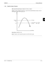
High Condenser Pressure
Alarm description (as shown on screen):
Cond Pressure High N.
Trigger:
Condenser Saturated Temperature is higher than the Max Saturated Condenser Value for
time longer than High Cond Delay set point.
Action Taken:
Rapid stop circuit.
Reset:
This alarm can be cleared manually via the Unit Controller keypad.
Setpoint
20.5
HP Alarm
If HP is below
this value
possible
to reset
15.5
HP
Time
Summary of Contents for EWAD620-C17C-SL
Page 2: ......
Page 8: ...ESIE10 01 1 2 Part 1 System Outline 3 1 1 5 ...
Page 111: ...ESIE10 01 General Outline Part 1 System Outline 1 105 3 1 4 5 1 36 1 Power Compressor 1 2 ...
Page 112: ...General Outline ESIE10 01 1 106 Part 1 System Outline 3 1 1 4 5 1 36 2 Power Compressor 3 ...
Page 113: ...ESIE10 01 General Outline Part 1 System Outline 1 107 3 1 4 5 1 36 3 Kit Pumps ...
Page 122: ...General Outline ESIE10 01 1 116 Part 1 System Outline 3 1 1 4 5 1 36 12 Digital Inputs Board ...
Page 123: ...ESIE10 01 General Outline Part 1 System Outline 1 117 3 1 4 5 1 36 13 Digital Outputs Board ...
Page 124: ...General Outline ESIE10 01 1 118 Part 1 System Outline 3 1 1 4 5 1 36 14 Digital Outputs Board ...
Page 131: ...ESIE10 01 General Outline Part 1 System Outline 1 125 3 1 4 5 1 36 21 EEXV Compressor 1 ...
Page 134: ...General Outline ESIE10 01 1 128 Part 1 System Outline 3 1 1 4 5 1 36 24 EEXV Compressor 2 ...
Page 137: ...ESIE10 01 General Outline Part 1 System Outline 1 131 3 1 4 5 1 36 27 EEXV Compressor 3 ...
Page 138: ...General Outline ESIE10 01 1 132 Part 1 System Outline 3 1 1 4 5 1 36 28 Pumps Control ...
Page 139: ...ESIE10 01 General Outline Part 1 System Outline 1 133 3 1 4 5 1 36 29 Terminals M1 M2 ...
Page 140: ...General Outline ESIE10 01 1 134 Part 1 System Outline 3 1 1 4 5 1 36 30 Terminals M3 ...
Page 141: ...ESIE10 01 General Outline Part 1 System Outline 1 135 3 1 4 5 1 36 31 Terminals M5 MQ ...
Page 148: ...General Outline ESIE10 01 1 142 Part 1 System Outline 3 1 1 4 5 ...
Page 150: ...ESIE10 01 2 2 Part 2 Functional Description 3 1 2 5 ...
Page 170: ...The Digital Controller ESIE10 01 2 22 Part 2 Functional Description 3 1 2 4 5 ...
Page 200: ...Functional Control ESIE10 01 2 52 Part 2 Functional Description 3 1 2 4 5 ...
Page 202: ...ESIE10 01 3 2 Part 3 Troubleshooting 3 1 3 5 ...
Page 254: ...Alarms and Events ESIE10 01 3 54 Part 3 Troubleshooting 3 1 3 4 5 ...
Page 266: ...Controller Inputs and Outputs ESIE10 01 3 66 Part 3 Troubleshooting 3 1 3 4 5 ...
Page 280: ...ESIE10 01 4 2 Part 4 Commissioning and Test Run 3 1 4 5 ...
Page 286: ...Pre Test Run Checks ESIE10 01 4 8 Part 4 Commissioning and Test Run 3 1 4 5 ...
Page 289: ...ESIE10 01 Running Data Part 4 Commissioning and Test Run 4 11 3 4 5 1 ...
Page 290: ...Running Data ESIE10 01 4 12 Part 4 Commissioning and Test Run 3 1 4 5 ...


