SYSTEM OPERATION
8
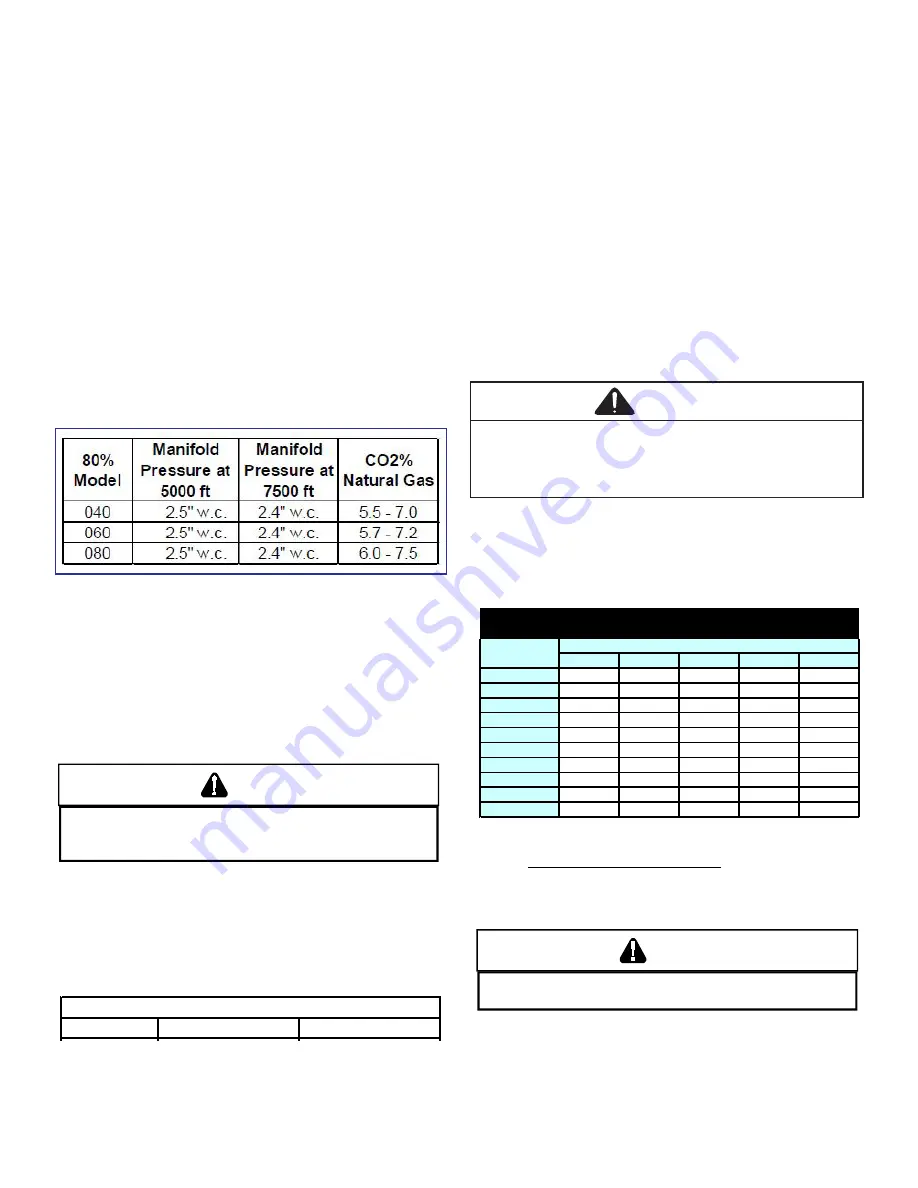
HIGH ALTITUDE
The furnace, as shipped, requires no change to run
between 0-4500 feet. at all altitudes the air temperature
rise must be within the range listed on the specification
sheet applicable to your model for the fuel used. manifold
pressure adjustments and combustion analysis are
required for all installations above 4500 ft. refer to “gas
supply pressure measurement” section for instruction
on how to properly measure and adjust manifold “outlet”
pressure. the furnace should operate for a minimum of 15
minutes before taking a combustion sample. combustion
samples should be taken from beyond the furnace
exhaust and must be within provided CO2% range. see
the following table for recommended manifold pressure
adjustments and proper CO2% range. gas heating values
can vary; further pressure adjustment may be necessary
to ensure furnace operates within acceptable CO2 range.
GAS SUPPLY AND PIPING
The furnace rating plate includes the approved furnace gas
input rating and gas types. The furnace must be equipped
to operate on the type of gas applied. This includes any
conversion kits required for alternate fuels and/or high
altitude.
CAUTION
T
O PREVENT UNRELIABLE OPERATION OR EQUIPMENT DAMAGE, THE INLET
GAS SUPPLY PRESSURE MUST BE AS SPECIFIED ON THE UNIT RATING PLATE
WITH ALL OTHER HOUSEHOLD GAS FIRED APPLIANCES OPERATING.
Inlet gas supply pressures must be maintained within the
ranges specified below. The supply pressure must be
constant and available with all other household gas fired
appliances operating. The minimum gas supply pressure
must be maintained to prevent unreliable ignition. The
maximum must not be exceeded to prevent unit overfiring.
Natural Gas
Minimum: 4.5" w.c.
Maximum: 10.0" w.c.
Propane Gas Minimum: 11.0" w.c. Maximum: 13.0" w.c.
INLET GAS SUPPLY PRESSURE
GAS VALVE
This unit is equipped with a 24 volt gas valve controlled
during furnace operation by the integrated control module.
Taps for measuring the gas supply pressure and manifold
pressure are provided on the valve.
NOTE: The gas supply pressure on White-Rodger "J"
model gas valve, used on single stage furnaces, can be
checked with a gas pressure test kit (Part #0151K00000S)
available through our authorized distributors.
The gas valve has a manual ON/OFF control located on the
valve itself. This control may be set only to the “ON” or “OFF”
position. Refer to the
Lighting Instructions Label
section of
this manual or the installation instructions for use of this
control during start up and shut down periods.
GAS PIPING CONNECTIONS
CAUTION
To avoid possible unsatisfactory operation or
equipment damage due to underfiring of equipment,
use the proper size of natural gas piping needed when
running pipe from the meter to the furnace.
The gas piping supplying the furnace must be properly sized
based on the gas flow required, specific gravity of the gas,
and length of the run. The gas line installation must comply
with local codes, or in their absence, with the latest edition
of the National Fuel Gas Code, NFPA 54/ANSI Z223.1.
Length of
Nominal Black Pipe Size
Pipe in Feet
1/2"
3/4"
1"
1 1/4"
1 1/2"
10
132
278
520
1050
1600
20
92
190
350
730
1100
30
73
152
285
590
980
40
63
130
245
500
760
50
56
115
215
440
670
60
50
105
195
400
610
70
46
96
180
370
560
80
43
90
170
350
530
90
40
84
160
320
490
100
38
79
150
305
460
CFH =
(Pressure 0.5 psig or less and pressure drop of 0.3" W.C.; Based on 0.60 Specific
Gravity Gas)
Natural Gas Capacity of Pipe
In Cubic Feet of Gas Per Hour (CFH)
BTUH Furnace Input
Heating Value of Gas (BTU/Cubic Foot)
CAUTION
E
DGES OF SHEET METAL HOLES MAY BE SHARP.
U
SE GLOVES A PRECAUTION
WHEN REMOVING HOLE PLUGS.
GAS PIPING CHECKS
Before placing unit in operation or upon completion of
servicing, leak test the unit and gas connections.
Summary of Contents for DM80SE
Page 15: ...TROUBLESHOOTING 15 DM80SE U...
Page 16: ...TROUBLESHOOTING 16 DM80SE U...


