MAINTENANCE
20
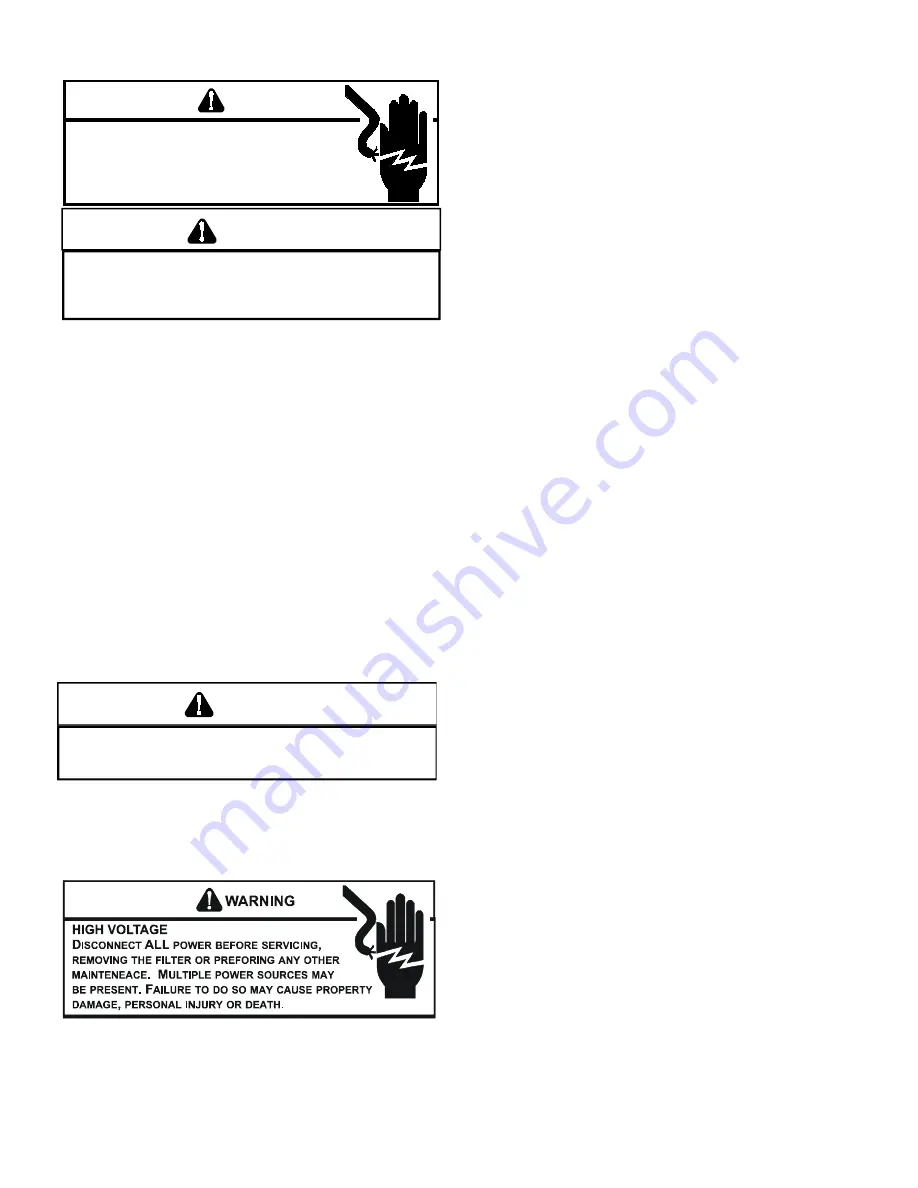
WARNING
HIGH
VOLTAGE
D
ISCONNECT
ALL
POWER BEFORE SERVICING OR
INSTALLING THIS UNIT.
M
ULTIPLE POWER SOURCES MAY
BE PRESENT.
F
AILURE TO DO SO MAY CAUSE PROPERTY
DAMAGE, PERSONAL INJURY OR DEATH.
I
F YOU MUST HANDLE THE ITNITOR, HANDLE WITH CARE.
T
OUCHING
THE IGNITOR BODY WITH BARE FINGERS, ROUGH HANDLING, OR
VIBRATION COULD RESULT IN EARLY IGNITOR FAILURE.
O
NLY A
QUALIFIED SERVICER SHOULD EVER HANDLE THE IGNITOR.
CAUTION
ANNUAL INSPECTION
The furnace should be inspected by a qualified installer, or
service agency at least once per year. This check should be
performed at the beginning of the heating season. This will
ensure that all furnace components are in proper working
order and that the heating system functions appropriately.
Pay particular attention to the following items. Repair or
service as necessary.
•
• Flue pipe system. Check for blockage and/or leakage.
Check the outside termination and the connections at
and internal to the furnace.
•
• Heat exchanger. Check for corrosion and/or buildup
within the heat exchanger passageways.
•
• Burners. Check for proper ignition and flame sense.
•
• Wiring. Verify that electrical connections are tight and
free from corrossion.
•
• Filters.
AIR FILTER
N
EVER OPERATE FURNACE WIHTOUT A FILTER INSTALLED AS DUST
AND LINT WILL BUILD UP ON INTERNAL PARTS RESULTING IN LOSS OF
EFFICIENCY, EQUIPMENT DAMAMGE, AND POSSIBLE FIRE.
WARNING
Filters must be used with this furnace. Filters do not ship
with these furnaces but must be provided by the installer for
proper furnace operation.
Dirty filters are the most common cause of inadequate
heating or cooling performance.
Maintenance
Improper filter maintenance is the most common cause of
inadequate heating or cooling performance. Filters should
be cleaned (permanent) or replaced (disposable) every two
months or as required.
Horizontal Unit Filter Removal
Filters in horizontal installations are located in the central
return register.
INDUCED DRAFT AND CIRCULATION BLOWERS
The bearings in the induced draft blower and circulator blower
motors are permanently lubricated by the manufacturer. No
further lubrication is required. Check motor windings for
accumulation of dust which may cause overheating. Clean
as necessary.
FLAME SENSOR (QUALIFIED SERVICER ONLY)
Under some conditions, the fuel or air supply can create a
nearly invisible coating on the flame sensor. This coating acts
as an insulator, causing a drop in the flame sensing signal.
If this occurs, a qualified servicer must carefully clean the
flame sensor with steel wool. After cleaning, the flame sensor
output should be as listed on the specification sheet.
The following is a must for every service technician and
service shop.
1. Dial type thermometers or thermocouple meter (op
-
tional) - to measure dry bulb temperature.
2. Volt-Ohm Meter - to measure amperage and voltage
and to test continuity, capacitors and motor windings.
3. Manometer - to measure static pressure, pressure
drop across coils, filters and draft and to test gas inlet
and manifold pressure.
Other recording type instruments can be essential in solving
abnormal problems, however, in many instances they may
be rented from local sources.
Proper equipment promotes faster, more efficient service and
accurate repairs resulting in fewer call backs.
HEATING PERFORMANCE TEST
Before attempting to diagnose an operating fault, run a
heating performance test and apply the results to the
Service
Problem Analysis Guide.
To conduct a heating performance test, the BTU input to the
furnace must be calculated.
After the heating cycle has been in operation for at least
fifteen minutes and with all other gas appliances turned off,
the gas meter should be clocked.
To find the BTU input, multiply the number of cubic feet of
gas consumed per hour by the heating value of the gas being
used. (The calorific value of the gas being used is found by
contacting your local utility.)
EXAMPLE:
It is found by the gas meter, that it takes forty
(40) seconds for the hand on the cubic foot dial to make
one complete revolution, with all appliances off, except
the furnace. Take this information and locate it on the gas
rate chart. Observe the forty (40) seconds, locate and read
across to the one (1) cubic foot dial column. There we find
the number 90, which shows that ninety (90) cubic feet of
gas will be consumed in one (1) hour.
Summary of Contents for DM80SE
Page 15: ...TROUBLESHOOTING 15 DM80SE U...
Page 16: ...TROUBLESHOOTING 16 DM80SE U...


