SYSTEM OPERATION
13
blower. The induced draft blower timing sequence
is not adjustable.
The integrated control module on all models provides
selectable fan on/off delay adjustments.
On/Off Fan Delay Selection
To change the fan on or off delay for COOLING, HP
HEATING & GAS HEATING modes, see the following
steps:
1. Press menu button until LED displays the desired on/off
setting (See MAIN MENU section for selectable blower
on/off delay options). Press option button and LED will
display the selected on/off delay time in seconds.
2. The control shall cycle through available on/off delay
times every time the option button is pressed.
3. When the menu button is pressed, the current displayed
on/off delay shall stop flashing. Press the menu
button again to select the option and the control shall
immediately apply that delay setting and return to the
corresponding main menu.
CIRCULATING AIR AND FILTERS
DUCTWORK - AIR FLOW
Duct systems and register sizes must be properly designed
for the C.F.M. and external static pressure rating of the
furnace. Ductwork should be designed in accordance with
the recommended methods of "Air Conditioning Contractors
of America" manual D.
A duct system should be installed in accordance with
Standards of the National Board of Fire Underwriters for
the Installation of Air Conditioning, Warm Air Heating and
Ventilating Systems, Pamphlets No. 90A and 90B.
A return air filter is not supplied with the furnace. The installer
or servicer must supply a means of filtering all of the return
air. Filter(s) shall comply with UL900 or CAN/ULC-S111
Standards.
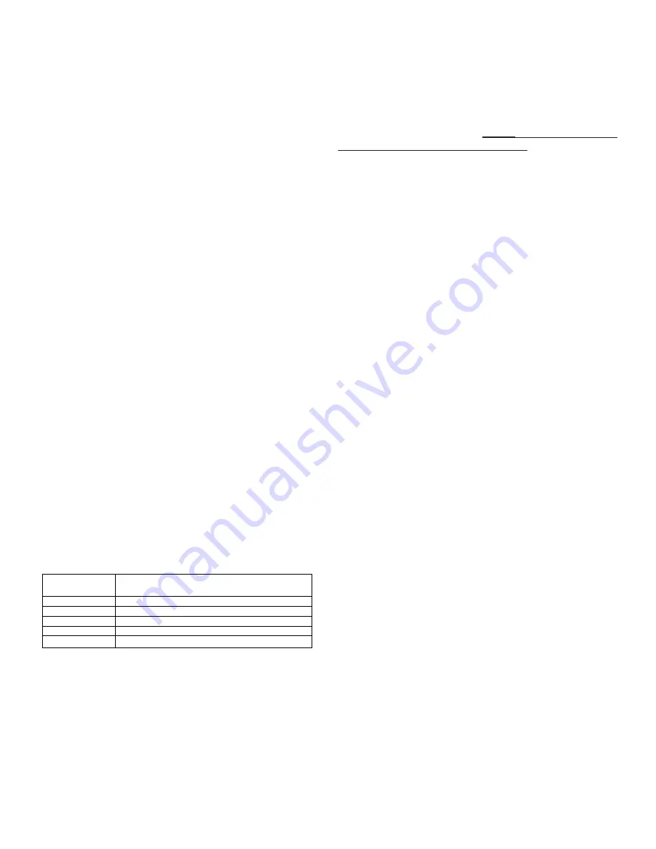
Upflow / Horizontal
Models
Minimum Recommended Filter Size^
*0403A*
1 - 16 X 25 Side or 1 - 14 X 24 Bottom Return
*0603A*
1 - 16 X 25 Side or 1 - 14 X 24 Bottom Return
*0604A*
1 - 16 X 25 Side or 1 - 16 X 25 Bottom Return
*0804A*
1 - 16 X 25 Side or 1 - 16 X 25 Bottom Return
*0805A*
2 - 16 X 25 Side or 1 - 20 X 25 Bottom Return
1
^Large filters may be used, filters may also be centrally located
1
= use 2- 16 X 25 filters and two side returns or 20 X 25 filter on bottom
return if furnace is connected to a cooling unit over 4 tons nominal capacity
Upflow furnaces with air delivery of less than 1800 CFM:
Use one side return or one bottom return ductwork connection.
Upflow furnaces with air delivery of 1800 CFM or higher:
Use two side returns or bottom return or combination of side/
bottom connection.
Guide dimples locate the side and bottom return cutout
locations. Use a straight edge to scribe lines connecting the
dimples. Cut out the opening on these lines. An undersized
opening will cause reduced airflow. For bottom return
connection, remove the bottom of the cabinet before setting
the furnace on the raised platform or return air duct.
A closed return duct system must be used, with the return
duct connected to the furnace.
NOTE:
Ductwork must never
be attached to the back of the furnace.
Supply and return
connections to the furnace may be made with flexible joints
to reduce noise transmission, if desired. If a central return is
used, a connecting duct must be installed between the unit
and the utility room wall so the blower will not interfere with
combustion air or draft. The room, closet, or alcove must not
be used as a return air chamber.
When the furnace is used in connection with a cooling unit,
the furnace should be installed in parallel with or on the
upstream side of the cooling unit to avoid condensation in
the heating element. With a parallel flow arrangement, the
dampers or other means used to control the flow of air must
be adequate to prevent chilled air from entering the furnace
and, if manually operated, must be equipped with means to
prevent operation of either unit unless the damper is in the
full heat or cool position.
When the furnace is heating, the temperature of the return
air entering the furnace must be between
55°F
and
100°F
.
UPRIGHT FILTER INSTALLATIONS
Depending on the installation and/or customer preference,
differing filter arrangements can be applied. Filters can
be installed in the central return register and a side panel
external filter rack kit (upflow filter kit # EFR01). As an
alternative a media air filter or electronic air cleaner can be
used as the requested filter. Refer to the following minimum
filter requirement charts for determination of the minimum
filter area to ensure proper unit performance.
ADDITIONAL FILTERING ACCESSORIES
External Filter Rack Kit (EFR01)
The external filter rack kit is intended to provide a location
external to the furnace casing, for installation of a permanent
filter on upflow model furnaces. The rack is designed to mount
over the indoor blower compartment area of either side panel,
and provide filter retention as well as a location for attaching
return air ductwork.
NORMAL SEQUENCE OF OPERATION
Power Up
•
120 VAC power applied to furnace.
•
Integrated ignition control performs internal checks.
•
LED light will flash once at power up and then remain on.
•
Integrated ignition control monitors safety circuit
continuously.
•
Furnace awaits call from thermostat.
Heating Mode
The normal operational sequence in heating mode is as
follows:
Summary of Contents for DM80SE
Page 15: ...TROUBLESHOOTING 15 DM80SE U...
Page 16: ...TROUBLESHOOTING 16 DM80SE U...