Installer reference guide
7
DCC601A51
intelligent Tab Controller
4P420109-1 – 2015.10
5.3.2.
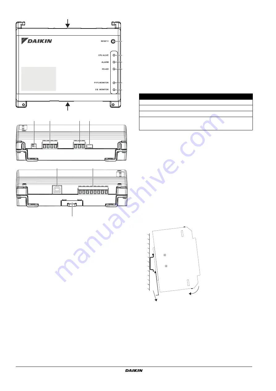
I/O module
Connectors
h
[DIII (F1/F2) and P1P2 (P1/P2)]
2×2 communication lines, connecting the intelligent Tab
Controller with DIII-compatible units and P1P2-compatible units
respectively.
The P1P2 connection is reserved for future use.
i [RS-485]
Reserved for future use.
k [CPU
IF]
USB 2.0 type-B socket. To connect with the CPU
module. Acts as a power supply and communication channel for
the I/O module.
l [Di1-4
and
Do]
Terminals for connecting digital inputs (Di) and
digital outputs (Do).
The Do connection is reserved for future use.
Controls and switches
a [RESET]
Reserved for future use.
g [DIII
MASTER]
Switch for setting the intelligent Tab Controller to
"MASTER" or "SLAVE" in a DIII-NET configuration.
Factory default: left position (MASTER).
j [DIP
SW]
Mode selector.
Factory default: bit 1 is set to: "on"; bits 2-4 are set to: "off".
m [Lever]
To assist mounting / dismounting the module onto / from
a DIN rail.
LEDs
b [CPU
ALIVE]
(Green) This LED blinks when the I/O module
operates normally. For details on LED operations, refer to the
"LED status and operation table (I/O module)" on page 7
c [ALARM]
(Red) This LED is lit or blinks if a failure is detected.
For details on LED operations, refer to the
operation table (I/O module)" on page 7
.
d [RS-485]
(Orange) This LED blinks when data is being
sent or received over the RS-485 port.
e [P1P2
MONITOR]
(Orange) This LED blinks when data is being
sent or received via the P1P2 line.
f [DIII
MONITOR]
(Orange) This LED blinks when DIII-NET
communication is performed.
LED status and operation table (I/O module)
6.
Installation of the intelligent Tab
Controller hardware
The intelligent Tab Controller components are to be mounted onto a
35 mm DIN rail, inside an electrical cabinet. For more information,
refer to
"5.2.1. Installation place and mounting direction" on page 5
.
Install the three intelligent Tab Controller hardware components as
follows:
1
Place the module over the top of the DIN-35 rail so that the
upper hook on the rear face is hooked in.
2
Push the module in direction 'a' until the lower hook snaps into
the rail.
3
If necessary, pull the lever on the lower parts of the module in
direction 'b' to click the module onto the rail. Use a flat-blade
screwdriver if necessary.
4
Repeat the previous steps for all other modules.
A
B
a
b
c
d
e
f
j
i
h
g
A
B
k
l
m
Operating condition
CPU ALIVE
ALARM
Normal
Blink
Off
Hardware failure
Off
On
Power interruption
Off
Off
Communication failure between
CPU module and I/O module
(for 10 seconds or more)
On
Blink
a
b


