background image

6

B10259-216

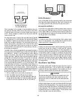
CO can cause serious illness including permanent brain

damage or death.

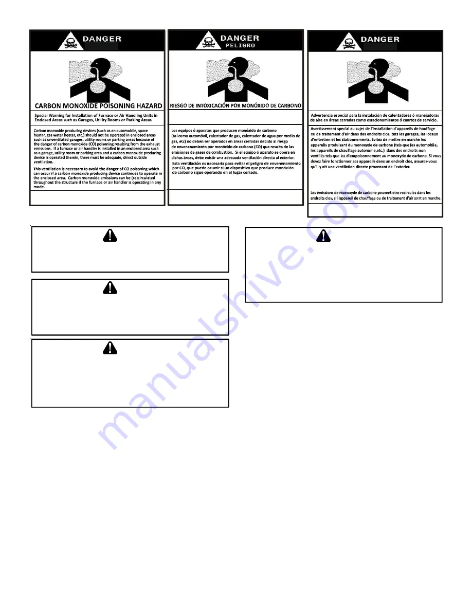
Advertencia especial para la instalación de calentadores ó manejadoras 

de aire en áreas cerradas como estacionamientos ó cuartos de servicio.

B10259-216

El monóxido de carbono puede causar enfermedades severas 
como  daño cerebral permanente ó muerte.

Las emisiones de monóxido de carbono pueden circular a través
del aparato cuando se opera en cualquier modo. 

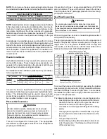
B10259-216

RISQUE D'EMPOISONNEMENT AU MONOXYDE DE CARBONE

Le monoxyde de 
des 

carbone peut causer des maladies graves telles que

dommages permanents au cerveau et meme la mort.

Cette ventilation est nécessaire pour éviter le danger d'intoxication
au CO pouvant survenir si un appareil produisant du monoxyde 
de carbone continue de fonctionner au sein de la zone confinée.

T

O


PREVENT


PERSONAL


INJURY


OR


DEATH


DUE


TO


ASPHYXIATION

THIS


FURNACE


MUST


BE

 C

ATEGORY

 I 

VENTED

. D

O


NOT


VENT


USING


C

ATEGORY

 III 

VENTING

.

P

ROVISIONS


MUST


BE


MADE


FOR


VENTING


COMBUSTION


PRODUCTS


OUTDOORS


THROUGH


A


PROPER


VENTING


SYSTEM

. T

HE


LENGTH


OF


FLUE


PIPE


COULD


BE


A


LIMITING


FACTOR


IN


LOCATING


THE


FURNACE

.

WARNING

A

DDITIONAL

 S

AFETY

 C

ONSIDERATIONS

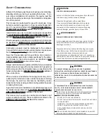
This furnace is approved for Category I Venting only.

Provisions must be made for venting combustion
products outdoors through a proper venting system.
The length of flue pipe could be a limiting factor in
locating the furnace.

S

HOULD


OVERHEATING


OCCUR


OR


THE


GAS


SUPPLY


FAIL


TO


SHUT


OFF

TURN


OFF


THE


MANUAL


GAS


SHUTOFF


VALVE


EXTERNAL


TO


THE


FURNACE


BEFORE


TURNING


OFF


THE


ELECTRICAL


SUPPLY

.

WARNING

P

OSSIBLE


PROPERTY


DAMAGE

PERSONAL


INJURY


OR


DEATH


DUE


TO


FIRE

EXPLOSION

SMOKE

SOOT

CONDENSATION

ELECTRICAL


SHOCK


OR


CARBON


MONOXIDE


MAY


RESULT


FROM


IMPROPER


INSTALLATION

REPAIR


OPERATION

OR


MAINTENANCE


OF


THIS


PRODUCT

.

WARNING

T

O


PREVENT


PERSONAL


INJURY


OR


DEATH


DUE


TO


IMPROPER


INSTALLATION

ADJUSTMENT

ALTERATION

SERVICE


OR


MAINTENANCE

REFER


TO


THIS


MANUAL

. F

OR


ADDITIONAL


ASSISTANCE


OR


INFORMATION

CONSULT


A


QUALIFIED


INSTALLER

SERVICER


AGENCY


OR


THE


GAS


SUPPLIER

.

WARNING

S

HIPPING

 I

NSPECTION

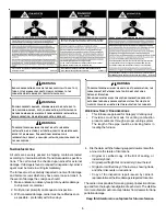
All units are securely packed in shipping containers tested
according to International Safe Transit Association specifica-
tions.  The carton must be checked upon arrival for external
damage.  If damage is found, a request for inspection by carrier’s
agent must be made in writing immediately.

The furnace must be carefully inspected on arrival for damage
and bolts or screws which may have come loose in transit.  In
the event of damage the consignee should:

1. Make a notation on delivery receipt of any visible damage

to shipment or container.

2. Notify carrier promptly and request an inspection.

3. With concealed damage, carrier must be notified as soon

as possible -  preferably within five days.

4. File the claim with the following support documents within

a nine month statute of limitations.

• Original or certified copy of the Bill of Lading, or

indemnity bond.

• Original paid freight bill or indemnity in lieu thereof.

• Original or certified copy of the invoice, showing trade

and other discounts or reductions.

• Copy of the inspection report issued by carrier’s

representative at the time damage is reported to carrier.

The carrier is responsible for making prompt inspection of dam-
age and for a thorough investigation of each claim. The distribu-
tor or manufacturer will not accept claims from dealers for trans-
portation damage.

Keep this literature in a safe place for future reference.

Summary of Contents for DC80VC

Page 1: ... follow them The precautions listed in this Installation Manual are intended as supplemental to existing practices However if there is a direct conflict between existing practices and the content of this manual the precautions listed here take precedence RECOGNIZE THIS SYMBOL AS A SAFETY PRECAUTION ONLY PERSONNEL THAT HAVE BEEN TRAINED TO INSTALL ADJUST SERVICE OR REPAIR HEREINAFTER SERVICE THE EQ...

Page 2: ...NSTALLATION 15 FIX 1 LINER TERMINATION 15 FIX 2 CHANGE VENTING ARRANGEMENTS 15 FIX 3 REBUILD THE CROWN 16 FIX 4 RELINING 16 ELECTRICAL CONNECTIONS 16 WIRING HARNESS 17 115 VOLT LINE CONNECTIONS 17 JUNCTION BOX RELOCATION 17 24 VOLT THERMOSTAT WIRING 18 FOSSIL FUEL APPLICATIONS 18 SINGLE STAGE HEATING THERMOSTAT APPLICATION 18 24 VOLT DEHUMIDISTAT WIRING 19 FOSSIL FUEL APPLICATIONS 19 115 VOLT LINE...

Page 3: ...SEQUENCE OF OPERATION 36 POWER UP 36 HEATING MODE 36 COOLING MODE 38 FAN ONLY MODE 38 OPERATIONAL CHECKS 38 SAFETY CIRCUIT DESCRIPTION 38 INTEGRATED CONTROL MODULE 39 PRIMARY LIMIT 39 AUXILIARY LIMIT 39 ROLLOUT LIMIT 39 PRESSURE SWITCHES 39 FLAME SENSOR 39 TROUBLESHOOTING 39 ELECTROSTATIC DISCHARGE ESD PRECAUTIONS 39 DIAGNOSTIC CHART 39 FAULT RECALL 39 FAULT CLEAR SEQUENCE 39 RESETTING FROM LOCKOU...

Page 4: ...in the LOCATION REQUIREMENTS AND CONSIDERATIONS section of this manual This furnace may be used as a construction site heater only if certain conditions are met These conditions are listed in the PRODUCT APPLICATION section of this manual TO PREVENT PERSONAL INJURY OR DEATH DUE TO IMPROPER INSTALLATION ADJUSTMENT ALTERATION SERVICE OR MAINTENANCE REFER TO THIS MANUAL FOR ADDITIONAL ASSISTANCE OR I...

Page 5: ...PERATURES AND WILL BE VACANT ALL WATER BEARING PIPES SHOULD BE DRAINED THE BUILDING SHOULD BE PROPERLY WINTERIZED AND THE WATER SOURCE CLOSED IN THE EVENT THAT THE BUILDING MAY BE EXPOSED TO FREEZING TEMPERATURES AND WILL BE VACANT ANY HYDRONIC COIL UNITS SHOULD BE DRAINED AS WELL AND IN SUCH CASE ALTERNATIVE HEAT SOURCES SHOULD BE UTILIZED WARNING TO PREVENT POSSIBLE PROPERTY DAMAGE PERSONAL INJU...

Page 6: ...TO FIRE EXPLOSION SMOKE SOOT CONDENSATION ELECTRICAL SHOCK OR CARBON MONOXIDE MAY RESULT FROM IMPROPER INSTALLATION REPAIR OPERATION OR MAINTENANCE OF THIS PRODUCT WARNING TO PREVENT PERSONAL INJURY OR DEATH DUE TO IMPROPER INSTALLATION ADJUSTMENT ALTERATION SERVICE OR MAINTENANCE REFER TO THIS MANUAL FOR ADDITIONAL ASSISTANCE OR INFORMATION CONSULT A QUALIFIED INSTALLER SERVICER AGENCY OR THE GAS...

Page 7: ...following final construction clean up by a qualified person ELECTROSTATIC DISCHARGE ESD PRECAUTIONS NOTE Discharge body s static electricity before touching unit An electrostatic discharge can adversely affect electrical com ponents Use the following precautions during furnace installation and servicing to protect the integrated control module from dam age By putting the furnace the control and th...

Page 8: ...al J Load Cal culations published by the Air Conditioning Contractors of America In the USA this furnace MUST be installed in accordance with the latest edition of theANSI Z223 1 booklet entitled National Fuel Gas Code NFPA 54 and the requirements or codes of the local utility or other authority having jurisdiction Additional helpful publications available from the NFPA are NFPA 90A Installation o...

Page 9: ...roximately 1 1 2 larger than the base of the furnace Ensure upflow or horizontal furnaces are not installed directly on carpeting or any other combustible material The only combustible material allowed is wood Exposure to contaminated combustion air will result in safety and performance related problems Do not install the furnace where the combustion air is exposed to the following substances chlo...

Page 10: ...REATER SHOULD TAKE PRECEDENCE OVER MINIMUM FIRE PRO TECTION CLEARANCE Agas fired furnace for installation in a residential garage must be installed so that the ignition source and burners are located not less than eighteen inches 18 above the floor and is protected or located to prevent physical damage by vehicles A gas furnace must not be installed di rectly on carpeting tile or other combustible...

Page 11: ...n marche alors que tous les autres appareils raccordés au système de ventilation ne sont pas en marche 1 Sceller toutes les ouvertures inutilisées du système de ventilation 2 Inspecter le système de ventilation afin de vérifier si la taille et l inclinaison par rapport à l horizontale sont conformes aux exigences du National Fuel Gas Code ANSI Z223 1 NFPA 54 ou du Code d installation du gaz nature...

Page 12: ...ge from the right side of the cabinet When rotating the inducer a chimney transition bottom kit part 0270F01119 is needed for proper alignment of the inducer out let and the vent exit hole in the side of the cabinet The inducer may NOT be rotated on CVC8 model furnaces regardless of installation position THIS PRODUCT IS NOT DESIGNED FOR COUNTERCLOCK WISE INDUCED DRAFT BLOWER ROTATION Vent the furn...

Page 13: ...mperatures have a direct impact on the suitability of this type of venting In most situations the existing masonry chimneys will require a properly sized metallic liner POSSIBILITY OF PROPERTY DAMAGE PERSONAL INJURY OR DEATH DAMAGING CONDENSATION CAN OCCUR INSIDE MASONRY CHIMNEYS WHEN A SINGLE FAN ASSISTED CATEGORY I APPLIANCE 80 AFUE FURNACE IS VENTED WITHOUT ADEQUATE DILUTION AIR DO NOT CONNECT ...

Page 14: ...the lowest existing vent connector and examine the inside of the elbow or tee at the base of the liner Asmall amount of soot may be considered acceptable provided the installer vacuums it away If rusted pieces of the liner have collected here the metal liner must be removed and replaced Fix 4 Next gently tap the inside of the liner with a Phillips screw driver If the screwdriver perforates the lin...

Page 15: ...ugh PVC pipe Next use a flashlight and small mirror to sight up the liner B vent must be supported so as to not come into direct contact with the chimney walls or tile liner If it is not it can probably be rehung so as to be acceptable A thimble or fire stop may be helpful here Flexible liners should be hung straight or nearly straight If it is spiraled in the chimney and in good condition it shou...

Page 16: ...SA B149 2 latest editions and amendments To install the liner read and follow the liner manufacturer s in structions and your local codes Excess liner length should be pulled out of the chimney and cut off Use caution when doing this as the cut edges of flexible liners may be sharp Do not spiral excess liner inside of the chimney Support the liner as recommended by the liner manufacturer Some manu...

Page 17: ... configured for a right side electrical connection To make electrical connections through the opposite side of the furnace the junction box must be relocated to the left side prior to making electrical connec tions To relocate the junction box perform the following steps TO PREVENT PERSONAL INJURY OR DEATH DUE TO ELECTRIC SHOCK DISCONNECT ELECTRICAL POWER BEFORE INSTALLING OR SERVICING THIS UNIT W...

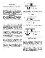
Page 18: ...Volt wiring NOTE For single stage cooling applications a jumper may be located between Y1 and Y2 at the furnace control in order to achieve the desired single stage cooling airflow Use of ramp ing profiles and dehumidification features requires a jumper between Y1 and O when the condensing unit is cooling only NOTE Thermostat R requiredifoutdoorunitisequippedwith a Comfort Alert module or if the o...

Page 19: ...EHUM TRIM ENABLE Move to the ON position to enable dehumidification ON OFF S5 FOSSIL FUEL APPLICATIONS This furnace can be used in conjunction with a heat pump in a fossil fuel application A fossil fuel application refers to a com bined gas furnace and heat pump installation which uses an outdoor temperature sensor to determine the most cost effi cient means of heating heat pump or gas furnace A h...

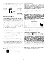
Page 20: ... NEUTRAL HUM OUT HUM IN 24VOLT HUMIDIFIER A 24 volt humidifier can be powered by feeding one of the HUM terminals with a field installed wire from the R terminal or by connecting to the NO side of the low fire pressure switch AUXILIARY ALARM SWITCH The control is equipped with a 24VACAuxiliaryAlarm Input 12 inch purple wire attached to pin 6 of 15 pin connector which can be utilized with communica...

Page 21: ... This unit is configured for natural gas The appropriate manufacturer s propane gas conversion kit must be applied for propane gas installations If converting to LP gas it is recommended that an LPLP0 kit also be installed The use of this kit will prevent the furnace from firing when the LP gas supply pressure is too low to sup port proper combustion GASPIPING CONNECTIONS TO AVOID POSSIBLE UNSATIS...

Page 22: ...rough the left side of the furnace the installer must supply the following fittings starting from the gas valve 90 degree elbow Straight pipe to reach the exterior of the furnace A ground joint union drip leg and manual shutoff valve must also be supplied by the installer In some cases the installer may also need to supply a transition piece from 1 2 inch to another pipe size COUNTERFLOWINSTALLATI...

Page 23: ... 430 830 1 300 2 100 830 1 900 175 170 400 780 1 200 1 900 770 1 700 200 160 380 730 1 100 1 800 720 1 500 Sizing Between First and Second Stage Regulator Maxim um Propane Capacities listed are based on 2 psig pressure drop at 10 psig setting Capacities in 1 000 BTU hour Nominal Pipe Size Schedule 40 Tubing Size O D Type L Pipe or Tubing Length Feet 3 8 1 2 5 8 3 4 7 8 1 1 8 1 2 3 4 1 1 1 4 1 1 2 ...

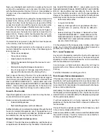
Page 24: ... much external static pressure will result in insufficient air that can cause excessive temperature rise This can cause limit switch tripping and heat exchanger failure To determine total external duct static pressure proceed as follows 1 With clean filters in the furnace use a draft gauge inclined manometer to measure the static pressure of the return duct at the inlet of the furnace Negative Pre...

Page 25: ... used filters may also be centrally located 1 use 2 16X 25filters and two side returns or 20X 25filter on bottomreturn if furnace is connected to a cooling unit over 4tons nominal capacity Consider installing an air cleaner with deep pleated media filter at the time of furnace installation A deep pleated filter with a MERV rating of 8 minimum will often provide better filtration to protect equipme...

Page 26: ... the setting Set the heat anticipator setting to 0 7 amps Follow the thermostat manufacturer s instructions on how to adjust the heat anticipa tor setting FURNACEOPERATION Purge gas lines of air prior to startup Be sure not purge lines into an enclosed burner compartment Check for leaks using an approved chloride free soap and wa ter solution an electronic combustible gas detector or other approve...

Page 27: ...capacity 4 The display will continue to flash Ft until high capacity 100 is achieved Once achieved the display will show Ft without flashing A 5 minute timer will be started to al low sufficient opportunity for the gas pressure to be tested 5 If a call for heat is given or removed during the test the system will still operate until the 5 minute test time is com plete 6 During test mode if both pus...

Page 28: ...necessary ad justments to pressure regulator gas piping size etc and or consult with local gas utility 5 Turn OFF gas to furnace at the manual shutoff valve and disconnect manometer Reinstall plug before turning on gas to furnace 6 Turn OFF any unnecessary gas appliances stated in step 3 Gas Line Gas Shutoff Valve Gas Line To Furnace Drip Leg Cap With Fitting Manometer Hose Manometer Open To Atmos...

Page 29: ...NPT hose barb fitting from the outlet pressure tap Replace the outlet pressure tap plug and seal with a high quality thread sealer b White Rodgers valve Turn outlet pressure test screw in to seal pressure port clockwise 7 in lb minimum 14 Turn on electrical power and gas supply to the system 15 Close thermostat contacts R and W1 W2 to energize the valve Using a leak detection solution or soap suds...

Page 30: ...r of seconds per cubic foot sec ft3 of gas being delivered to the furnace If the dial is a two cubic foot dial divide the number of seconds recorded in step 2 by two 4 Calculate the furnace input in BTUs per hour BTU hr Input equals the sum of the installation s gas heating value and a conversion factor hours to seconds divided by the number of seconds per cubic foot The measured input must not be...

Page 31: ...s or other devices may require specific air flows consult installa tion instructions of those devices for requirements 3 Knowing the furnace model locate the high stage cooling air flow charts in the Specification Sheet applicable to your model Look up the cooling air flow determined in step 2 and find the required cooling speed and adjustment setting Example A DM80VC0604BX furnace installed with ...

Page 32: ...FF DELAY TIMINGS The integrated control module provides a selectable heat off delay function The heat off delay period may be set to 90 120 150 180 seconds using the DIP switches or jumper provided on the control module The delay is factory shipped at 150 seconds but may be changed to suit the installation require ments and or homeowner preference Refer to the following fig ures for switch positio...

Page 33: ...manual for the airflow delivered during cooling or heat pump heating In continuous fan mode the CTK0 thermostat provides the airflow demand The thermostat may be configured for a low medium or high continuous fan speed The low medium and high fan speeds correspond to 25 50 and 75 respec tively of the furnaces maximum airflow capability During con tinuous fan operation the thermostat sends a fan re...

Page 34: ...ble Single Stage AC ComfortNet G W1 W2 Y1 Y2 O 1 2 R C 4 Position Connectors from CTK0 Thermostat Kit System Wiring between Furnace and Non Communicating CompatibleSingleStageAirConditioner NOTE When using a non communicating condenser cooling CFM will need to be set up in the communicating thermostat Go to the ComfortNet menu communicating equipment furnace setup non comm Select the condenser siz...

Page 35: ... heat demand Humidity Fan Speed 1 2 3 4 Select Humidity Fan Speed this option is enabled when Humidity Setting of IND is selected 1 25 2 50 3 75 4 100 of maximum airflow SET UP Submenu Item Indication User Modifiable Options Comments Fault 1 FAULT 1 Most recent furnace fault For display only Fault 2 FAULT 2 Next most recent furnace fault For display only Fault 3 FAULT 3 Next most recent furnace fa...

Page 36: ...0 in 2 increments default is 0 Selects the airflow trim amount for the non communicating compatible single stage AC unit Cool Airflow Profile CL PRFL A B C or D default is A Selects the airflow profile for the non communicating compatible single stage AC unit Cool ON Delay CL ON 5 10 20 or 30 seconds default is 5 seconds Selects the indoor blower ON delay for the non communicating compatible singl...

Page 37: ...unications Failure 2 Flashes Out of box reset Green Receive LED Off Nopower Communications error 1 Steady Flash No network found Rapid Flashing Normal network traffc On Solid Data 1 Data 2 miss wire Possible Cause Corrective Action Comments None None None Communications Failure Depress Learn Button Verify that bus BIAS and TERM dipswitches are in the ON position Depress once quickly for a power up...

Page 38: ... thermostat contacts open completing the call for cool Outdoor fan and compressor are de energized Circulator blower continues running during a cool off delay period The OFF delay time and airflow level are determined by the selected ramping profile Electronic air cleaner terminal and circulator blower are de energized Furnace awaits next call from thermostat FANONLY MODE The normal operational se...

Page 39: ...icable to both installed and uninstalled ungrounded furnaces 1 Disconnect all power to the furnace Do not touch the integrated control module or any wire connected to the control prior to discharging your body s electrostatic charge to ground 2 Firmly touch a clean unpainted metal surface of the furnace away from the control Any tools held in a person s hand during grounding will be discharged 3 S...

Page 40: ...er flame and flame signal Drainage system Check for blockage and or leakage Check hose connections at and internal to furnace Wiring Check electrical connections for tightness and or corrosion Check wires for damage Filters FILTERS TO ENSURE PROPER UNIT PERFORMANCE ADHERE TO THE FILTER SIZES GIVEN IN THE RECOMMENDED MINIMUM FILTER SIZE TABLE OR SPECIFICATION SHEET APPLICABLE TO YOUR MODEL CAUTION ...

Page 41: ...changer flue passageways should be inspected at the beginning of each heating season BEFORE LEAVING AN INSTALLATION Cycle the furnace with the thermostat at least three times Verify cooling and fan only operation Review the Owner s Manual with the homeowner and discuss proper furnace operation and maintenance Leave literature packet near furnace REPAIR AND REPLACEMENT PARTS When ordering any of th...

Page 42: ... for Service icon illuminated ComfortNet thermostat scrolls Check Furnace message E0 Furnace lockout due to an excessive number of ignition retries 3 total LOCKOUT E0 Failure to establish flame Cause may be no gas to burners front cover pressure switch stuck open bad igniter or igniter alignment improper Orifices or coated oxidized or improperly connected Flame sensor Loss of flame after establish...

Page 43: ... and ductwork for blockage Clean or remove filters obstruction Check circulator blower speed and performance Correct speed or replace blower motor if necessary Check burners for proper alignment Check fuel and air inlet piping for blockage proper length elbows and termination Correct as necessary Check induced draft blower for proper performance Replace if necessary Tighten or correct wiring conne...

Page 44: ...ed improperly Blocked fue and or inlet air pipe blocked drain system or weak induced draft blower Incorrect pressure switch set point or malfunctioning switch contacts Loose or improperly connected wiring Inspect pressure switch hose Repair replace if necessary Inspect fue and or inlet air piping for blockage proper length elbows and termination Check drain system Correct as necessary Check induce...

Page 45: ...ontrol module has lost communications with circulator blower motor MOTOR COMM b1 Loose wiring connection at circulator motor control leads Failed circulator blower motor Failed integrated control module Tighten or correct wiring connection Check circulator blower motor Replace if necessary Check integrated control module Replace if necessary Turn power OFF prior to repair Replace circulator motor ...

Page 46: ...at scrolls Check Furnace message b7 MOTOR PARAMS b7 Furnace operates at reduced performance or Integrated control module LED display provides b9 error code b9 LOW ID AIRFLOW B9 Blocked filters Restrictive ductwork Undersized ductwork Check filters for blockage Clean filters or remove obstruction Check ductwork for blockage Remove obstruction Verify all registers are fully open Verify ductwork is a...

Page 47: ...ED 115 VAC POLARITY DATANOT YET ON NETWORK INVALID MEMORYCARD DATA BLOWER MOTOR NOT RUNNING BLOWER COMMUNICATION ERROR BLOWER HP MIS MATCH BLOWER MOTOR OPERATING IN POWER TEMPERATURE OR SPEED LIMIT BLOWER MOTOR CURRENT TRIP OR LOST ROTOR BLOWER MOTOR LOCKED ROTOR OVER UNDER VOLTAGE TRIP OR OVER TEMPERATURE TRIP INCOMPLETE PARAMETERS SENT TO MOTOR LOW INDOOR AIRFLOW LOW STAGE COOL HIGH STAGE COOL L...

Page 48: ...Off Delay Short Run 30s ec 50 DC80VC0805C DM 80VC0803B DM 80VC0804C DM 80VC0805C Speed Selection Dip Switches C o o l Selec tio n Switc hes A djus t Selec tio n Switches P ro file Selec tio n Switc hes H eat Selec tio n Switc hes 60 sec 100 7 5 min 82 60 sec 100 To Set A irflow 1 Select model and des ired High Stage Cooling A irflow Determine the corres ponding tap A B C or D Set dip s witches S3 ...

Page 49: ...Add 5 Off Off Minus 5 On Off Add 10 Off On Minus 10 On On A Off Off B On Off C Off On D On On A Off Off B On Off C Off On D On On Disabled Off Enabled On Disabled Off Enabled On 25 Off Off 50 On Off 75 Off On 100 On On S5 Dehum Trim Continuous Fan S3 Cooling Airflow Trim S4 Ramping Profile Heating Airflow Switch Bank Purpose Function Dip Switch S1 Heating Off Delay Thermostat Setup ...

Page 50: ... 1800 C D 60 sec 100 7 5 min 82 60 sec 100 To Set Airflow 1 Select model and desired High Stage CoolingAirflow Determine the corresponding tap A B C or D Set dip switches S3 1 and S3 2 to the appropriate ON OFF positions 2 Select model and desired High Stage Heating Airflow Determine The corresponding tap A B C or D Set dip switches S4 3 and S4 4 to the appropriate ON OFF positions 3 Selecting Air...

Page 51: ...51 THIS PAGE LEFT INTENTIONALLY BLANK ...

Page 52: ... warranty protection except that failure by California and Quebec residents to register their product does not diminish their warranty rights For Product Registration please register by following this link https daikincomfort com owner support product registration You can also scan the QR code on the right to be directed to the Product Registration page CUSTOMERFEEDBACK Daikin is very interested i...

Reviews: