10
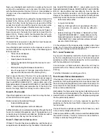
closet. DO NOT remove solid base plate for side return.
•
Return air ducts must be
completely
sealed to the
furnace and terminate outside the enclosure surfaces.
C
LEARANCES
AND
A
CCESSIBILITY
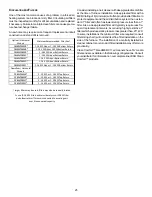
Clearance in accordance with local installation codes, the re-
quirements of the gas supplier and the manufacturer’s instal-
lation instructions.
Dégaugement conforme aux codes d’installation locaux, aux
exigences du fournisseur de gaz et aux instructions
d’installation du fabricant.
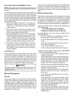
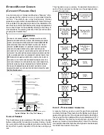
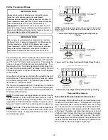
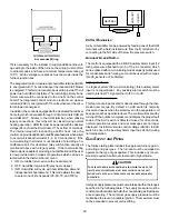
Unobstructed front clearance of 24"
for servicing
is recom-
mended.
T O P
B1-V EN T
S IN G LE
(P LE N U M )
1"
6"
1"
3"
0"
1"
VEN T
SID ES
F R O N T
B AC K
Top clearance for horizontal configuration - 1"
I
NSTALLATION
P
OSITIONS
DM80VC model furnaces may be installed vertically (upflow) or
horizontally with left or right side down. DC80VC model fur-
naces may be installed vertically (downflow) or hortizontally
with left or right side down. Do not install this furnace on its
back. For vertically installed
upflow
furnaces, return air ductwork
may be attached to the side panel(s) and/or basepan. For
hori-
zontally
installed
upflow
furnaces, return air ductwork must be
attached to the basepan. For
counterflow
furnaces, return
ductwork must be attached to the blower compartment end of
the furnace.
NOTE:
Ductwork must never be attached to the back of the
furnace.
H
ORIZONTAL
I
NSTALLATION
Line contact to framing is permitted when installed in the hori-
zontal configuration. Line contact is defined as the portion of
the cabinet that is formed by the intersection of the top and
side. ACCESSIBILITY CLEARANCE, WHERE GREATER,
SHOULD TAKE PRECEDENCE OVER MINIMUM FIRE PRO-
TECTION CLEARANCE. A gas-fired furnace for installation in
a residential garage must be installed so that the ignition source
and burners are located not less than eighteen inches (18")
above the floor and is protected or located to prevent physical
damage by vehicles. A gas furnace must not be installed di-
rectly on carpeting, tile, or other combustible materials other
than wood flooring.
F
URNACE
S
USPENSION
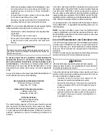
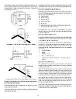
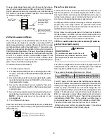
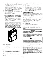
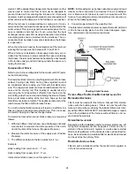
If suspending the furnace from rafters or joist, use 3/8" threaded
rod and 2”x2”x3/8” angle iron as shown below. The length of
rod will depend on the application and the clearances neces-
sary.
Suspended Furnace
E
XISTING
F
URNACE
R
EMOVAL
NOTE:
When an existing furnace is removed from a venting
system serving other appliances,
the venting system may be
too large to properly vent the remaining attached appliances.
T
HERMOSTAT
L
OCATION
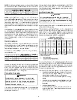
In an area having good air circulation, locate the thermostat
about five feet high on a vibration-free inside wall. Do not install
the thermostat where it may be influenced by any of the follow-
ing:
•
Drafts, or dead spots behind doors, in corners, or under
cabinets.
•
Hot or cold air from registers.
•
Radiant heat from the sun.
•
Light fixtures or other appliances.
•
Radiant heat from a fireplace.
•
Concealed hot or cold water pipes, or chimneys.
•
Unconditioned areas behind the thermostat, such as
an outside wall.
Consult the instructions packaged with the thermostat for mount-
ing instructions and further precautions.
C
OMBUSTION
AND
V
ENTILATION
A
IR
R
EQUIREMENTS
T
O
AVOID
PROPERTY
DAMAGE
,
PERSONAL
INJURY
OR
DEATH
,
SUFFICIENT
FRESH
AIR
FOR
PROPER
COMBUSTION
AND
VENTILATION
OF
FLUE
GASES
MUST
BE
SUPPLIED
. M
OST
HOMES
REQUIRE
OUTSIDE
AIR
BE
SUPPLIED
INTO
THE
FURNACE
AREA
.
WARNING


