27
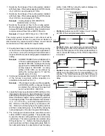
11. Adjust the thermostat to a setting above room
temperature.
12. After the burners are lit, set the thermostat to desired
temperature.
F
URNACE
S
HUTDOWN
1. Set the thermostat to the lowest setting.
The integrated control will close the gas valve and
extinguish flame. Following a 15 second delay, the
induced draft blower will be de-energized. After a 120,
150, 180 or 210-second delay period (field selectable
delay OFF [90, 120, 150, 180] plus 30-second ramp
down), the circulator blower de-energizes.
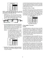
2. Remove the burner compartment door and move the
furnace gas valve manual control to the OFF position.
3. Close the manual gas shutoff valve external to the furnace.
4. Replace the burner compartment door.
G
AS
S
UPPLY
P
RESSURE
M
EASUREMENT
G
AS
P
RESSURE
T
EST
NOTE:
When removing a valve adjustment screw or a
pressure tap on a Honeywell gas valve, use a T-25 or 3/
16” flathead screwdriver.
DO NOT USE POWER
TOOLS.
This test is to be used for field test mode only, and it will allow
gas valve pressure to be checked at 100% firing rate.
1. If both ‘FAULT RECALL’ and ‘LEARN’ push buttons are
pressed for greater than 1 second, the display will blank to
indicate the push buttons are pressed. Within 5 seconds,
both push buttons should be released. If any push button is
not released, the test mode will not activate. The display
will return to normal.
2. Once the push buttons are released, the display will flash
“Ft” to indicate the push buttons are released and success-
ful entry into test mode has been achieved.
3. The control will force a high capacity demand. If a low ca-
pacity demand is already being serviced, it will be forced to
high capacity.
4. The display will continue to flash “Ft” until high capacity
(100%) is achieved. Once achieved, the display will show
“Ft” without flashing. A 5-minute timer will be started to al-
low sufficient opportunity for the gas pressure to be tested.
5. If a call for heat is given or removed during the test, the
system will still operate until the 5 minute test time is com-
plete.
6. During test mode, if both push buttons are pressed for
greater than 1 second, the display will blank to indicate
push buttons are pressed. If both push buttons are released
within 5 seconds, the test mode will terminate and the sys-
tem will return to normal operation. Otherwise, the test mode
will continue uninterrupted.
7. After completion of the 5-minute timer or test mode termi-
nation, whichever is earlier, the system will return to normal
operation, either continuing an existing heat demand or going
to the idle state.
CAUTION
T
O
PREVENT
UNRELIABLE
OPERATION
OR
EQUIPMENT
DAMAGE
,
THE
INLET
GAS
SUPPLY
PRESSURE
MUST
BE
AS
SPECIFIED
ON
THE
UNIT
RATING
PLATE
WITH
ALL
OTHER
HOUSEHOLD
GAS
FIRED
APPLIANCES
OPERATING
.
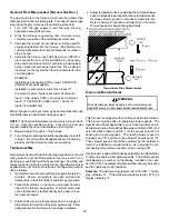
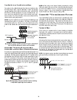
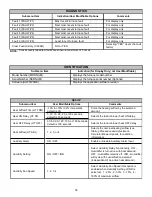
The line pressure supplied to the gas valve must be within the
range specified below. The supply pressure can be measured
at the gas valve inlet pressure tap or at a hose fitting installed in
the gas piping drip leg. The supply pressure must be mea-
sured with the burners operating. To measure the gas supply
pressure, use the following procedure.
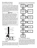
INLET
OUTLET
Gas Valve On/Off
Selector Switch
White-Rodgers Model 36J54 (Two-Stage)
Inlet
Pressure
Tap
Low Fire
Regulator
Adjust
Manometer
Manometer
Hose
High Fire Regulator
Adjust
Regulator
Vent
Outlet
Pressure Tap
Open to
Atmosphere
On/Off Switch
High Fire Coil
Terminal (HI)
Coaxial Coil
Terminal (M)
Common
Terminal(C)
White-Rodgers Model 36J54 Connected to Manometer

