background image

12

before starting drive. Recheck set screws and belt 

tension after 24 hours service.

NOTE:

 Future adjustments should be made by loosening

the belt tension and increasing or decreasing the pitch 

diameter of the sheave by half or full turns as required. 

Readjust belt tension before starting drive.
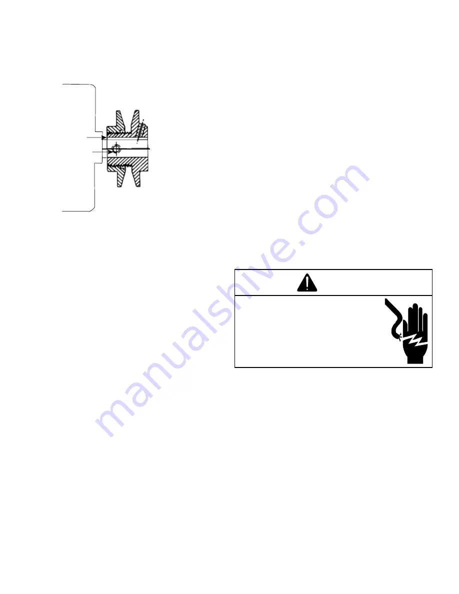
C

B

VL & VM

NOTE:

 Do NOT operate sheave with flange projecting 

beyond the hub end.

Refrigeration System Checks

This unit is equipped with thermal expansion valves. 

Ensure 

the hold-down bolts on the compressor are secure and 

have not vibrated loose during shipment. Check that the 

vibration grommets have been installed and visually check 

all piping for damage and leaks and repair if necessary. The 

entire system has been factory charged and tested, making 

it unnecessary to field charge. Factory refrigerant charge is 

shown on the unit’s nameplate.
To confirm charge levels or, if a leak occurs and charge needs 

to be added to the system, it is recommended to evacuate 

the system and recharge refrigerant to the unit’s nameplate 

specifications. This unit has been rated in the cooling mode at the 

AHRI rated conditions of: indoor (80°F db/67°F wb) and outdoor 

(95°F db). While operating at this condition, the superheat should 

range from 9°F to 11°F for each refrigeration circuit measured at 

the suction service port located near the compressor.

Start-Up Procedure and Checklist

Begin with power turned off at all disconnects.

Air Conditioning Start-Up Procedure

1.  Ensure the thermostat is set to OFF and Fan is set 

to Auto.  

2. 

Inspect all registers and set them to the normal open 

position.

3.  Turn on the electrical supply at the disconnect.
4.  Turn the fan switch to the “ON” position. The blower 

should operate after a 7 second delay. 

5.  Turn the fan switch to “Auto” position. The blower 

should stop after a 60 second delay.

6.  Set the thermostat to Cool mode and slowly 

lower the cooling temperature until the unit starts. 

The compressor, blower and fan should now be 

operating. Allow the unit to run 10 minutes, make 

sure cool air is being supplied by the unit.

7.  Check that the compressor is operating correctly. 

The scroll compressors in these units MUST operate 

in the proper rotation. To ensure the compressors 

are operating in the correct direction, check the 

compressor discharge line pressure or temperature 

after the compressor is started. The discharge 

pressure and discharge line temperature should 

increase. If this does not occur and the compressor 

is producing an exceptional amount of noise,this 

indicates that there is a phasing issue. 

Perform the following to correct: 

7.1  Turn power to the unit OFF.
7.2  Switch any two leads of power supply at unit 


Single Point Power Block.

7.3  Turn power to the unit ON.
7.4  Perform step 7 again.

8.  Turn the temperature setting to the highest position, 

stopping the unit. The indoor blower will continue to 

run for 60 seconds.

9.  Turn the thermostat system switch to “OFF” and 

disconnect all power when servicing the unit.

NOTE: The compressor has 180 second re-start 

delay on timer to avoid short cycling.

WARNING

HIGH VOLTAGE!

Disconnect all power before 

servicing or installing this unit. 

Multiple power sources may be 

present. Failure to do so may cause 

property damage, personal injury or 

death.

Heat Pump Start-Up Procedure 

10. 

Check the cooling mode for the heat pump in the 

same manner as above. The reversing valve is 

energized when the thermostat is placed in the 

cooling position. A clicking sound should be noticeable 

from the reversing valve. By lowering the temperature 

setting to call for cooling, the solenoid valve is 

energized. The compressor, blower and fan should 

then be running. After the cooling mode is checked 

out, turn the thermostat system switch to “OFF”.

11. Turn the thermostat system switch to “HEAT” and fan 

switch to “AUTO”. 

12. Slowly raise the heating temperature setting. When 

the heating first stage makes contact, stop raising the 

temperature setting.. The compressor, blower and fan 

should now be running with the reversing valve in the 

deenergized (heating) position. After giving the unit time 

to settle out, make sure the unit is supplying heated air.


Note: If the outdoor ambient is above 80°F, the unit 

may trip on its high pressure cut out when on heating. 

The compressor should stop. The heating cycle 

must be thoroughly checked, so postpone the test to 

Summary of Contents for DBC0363B Series

Page 1: ...t specified in this manual only licensed personnel should servise the equipment Improper installation adjustment servicing or repair of the equipment specified in this manual or attempting to install...

Page 2: ...ce CAUTION Sheet metal parts screws clips and similar items inherently have sharp edges and it is necessary that the installer and service personnel exercise caution WARNING Do not connect to or use a...

Page 3: ...ld also where applicable follow information presented in accepted industry guides such as the ASHRAE Handbooks The manufacturer assumes no responsibility for equipment installed in violation of any co...

Page 4: ...Installations Only To avoid possible property damage or personal injury the roof must have sufficient structural strength to carry the weight of the unit s and snow or water loads as required by local...

Page 5: ...ntenance and proper unit operation A clearance of 48 is recommended on all sides of the unit to facilitate possible parts replacement to allow service access and to insure proper ventilation and conde...

Page 6: ...to protect unit base frame from fork lift damage Removal is accomplished by extracting the sheet metal retainers and pulling the struts through the base of the unit Refer to rigging label on the unit...

Page 7: ...MUM OVERCURRENT DEVICE SIZE SHOWN ON UNIT DATA PLATE All line voltage connections must be made through weatherproof fittings All exterior power supply and ground wiring must be in approved weatherproo...

Page 8: ...f unit due to operation on improper line voltage or with excessive phase unbalance constitutes product abuse and is not covered by the warranty It may cause severe damage to the unit s electrical comp...

Page 9: ...may be required before entering thermostat sub base NOTE Refer to unit wiring diagrams for thermostat or remote sensor connections CIRCULATING AIR AND FILTERS Ductwork The supply duct from the unit t...

Page 10: ...d for temporary heating or cooling inspect the coils fans and motors for unacceptable levels of construction dust and dirt and install new filters Contractor Responsibility The installing contractor m...

Page 11: ...it is best to have a variable pitched motor sheave for the purpose of airflow balancing but once the balance has been achieved fixed sheaves maintain alignment and minimize vibration more effectively...

Page 12: ...ck that the compressor is operating correctly The scroll compressors in these units MUST operate in the proper rotation To ensure the compressors are operating in the correct direction check the compr...

Page 13: ...e by redirecting refrigerant flow through the refrigerant circuit external to the compressor This is accomplished by the reversing valve Hot discharge vapor from the compressor is directed to the indo...

Page 14: ...ilters should be cleaned or replaced These few steps will help to keep the product up time to a maximum The Service section that follows should help in identifying problems if the unit does not operat...

Page 15: ...STATIC BELT DRIVE DOWNSHOT ESP In H2 O TURNS OPEN 0 1 2 3 4 5 CFM RPM BHP CFM RPM BHP CFM RPM BHP CFM RPM BHP CFM RPM BHP CFM RPM BHP 0 7 1481 1020 0 57 0 8 1370 1020 0 53 0 9 1434 1080 0 62 1247 102...

Page 16: ...250 950 0 42 989 885 0 30 DBC036 C HIGH STATIC BELT DRIVE HORIZONTAL ESP In H2 O TURNS OPEN 0 1 2 3 4 5 CFM RPM BHP CFM RPM BHP CFM RPM BHP CFM RPM BHP CFM RPM BHP CFM RPM BHP 0 8 1539 1020 0 59 0 9 1...

Page 17: ...FM RPM BHP CFM RPM BHP CFM RPM BHP CFM RPM BHP CFM RPM BHP 0 6 1996 1200 1 05 1872 1135 0 88 1741 1075 0 74 0 7 1922 1200 1 01 1790 1135 0 84 1650 1075 0 70 0 8 1985 1265 1 17 1845 1200 0 97 1703 1135...

Page 18: ...HIGH STATIC BELT DRIVE HORIZONTAL ESP In H2 O TURNS OPEN 0 1 2 3 4 5 CFM RPM BHP CFM RPM BHP CFM RPM BHP CFM RPM BHP CFM RPM BHP CFM RPM BHP 0 6 1895 1075 0 81 0 7 1958 1135 0 93 1802 1075 0 76 0 8 18...

Page 19: ...BELT DRIVE DOWNSHOT ESP In H2 O TURNS OPEN 0 1 2 3 4 5 CFM RPM BHP CFM RPM BHP CFM RPM BHP CFM RPM BHP CFM RPM BHP 0 6 2237 1245 1 27 2072 1175 1 03 0 7 2333 1315 1 48 2164 1245 1 23 1990 1175 0 99 0...

Page 20: ...65 DBC060 C HIGH STATIC BELT DRIVE HORIZONTAL ESP In H2 O TURNS OPEN 0 1 2 3 4 5 CFM RPM BHP CFM RPM BHP CFM RPM BHP CFM RPM BHP CFM RPM BHP CFM RPM BHP 0 6 2394 1245 1 37 2239 1175 1 12 0 7 2320 1245...

Page 21: ...175 1 05 1900 1110 0 86 DBC072 S HIGH STATIC BELT DRIVE DOWNSHOT ESP In H2 O TURNS OPEN 0 1 2 3 4 5 CFM RPM BHP CFM RPM BHP CFM RPM BHP CFM RPM BHP CFM RPM BHP CFM RPM BHP 0 6 2630 1385 1 88 2492 1315...

Page 22: ...1110 0 84 DBC072 S HIGH STATIC BELT DRIVE HORIZONTAL ESP In H2 O TURNS OPEN 0 1 2 3 4 5 CFM RPM BHP CFM RPM BHP CFM RPM BHP CFM RPM BHP CFM RPM BHP CFM RPM BHP 0 6 2655 1385 1 90 2520 1315 1 62 2369 1...

Page 23: ...5 0 26 DBH036 C HIGH STATIC BELT DRIVE DOWNSHOT ESP In H2 O TURNS OPEN 0 1 2 3 4 5 CFM RPM BHP CFM RPM BHP CFM RPM BHP CFM RPM BHP CFM RPM BHP CFM RPM BHP 0 8 1587 1020 0 61 0 9 1456 1020 0 56 1 0 151...

Page 24: ...0 35 Note VL34 and AK61 pulleys used on standard static unit DBH036 C HIGH STATIC BELT DRIVE HORIZONTAL ESP In H2 O TURNS OPEN 0 1 2 3 4 5 CFM RPM BHP CFM RPM BHP CFM RPM BHP CFM RPM BHP CFM RPM BHP C...

Page 25: ...O TURNS OPEN 0 1 2 3 4 5 CFM RPM BHP CFM RPM BHP CFM RPM BHP CFM RPM BHP CFM RPM BHP CFM RPM BHP 0 6 2003 1075 0 85 0 7 1898 1075 0 81 0 8 1936 1135 0 91 1788 1075 0 76 0 9 1979 1200 1 05 1833 1135 0...

Page 26: ...RNS OPEN 0 1 2 3 4 5 CFM RPM BHP CFM RPM BHP CFM RPM BHP CFM RPM BHP CFM RPM BHP CFM RPM BHP 0 6 1885 1075 0 80 0 7 1955 1135 0 92 1791 1075 0 76 0 8 1865 1135 0 88 1691 1075 0 72 0 9 1948 1200 1 03 1...

Page 27: ...H2 O TURNS OPEN 0 1 2 3 4 5 CFM RPM BHP CFM RPM BHP CFM RPM BHP CFM RPM BHP CFM RPM BHP CFM RPM BHP 0 6 2397 1310 1 53 2278 1245 1 31 2145 1180 1 10 2003 1115 0 92 0 7 2334 1310 1 48 2208 1245 1 26 2...

Page 28: ...TURNS OPEN 0 1 2 3 4 5 CFM RPM BHP CFM RPM BHP CFM RPM BHP CFM RPM BHP CFM RPM BHP CFM RPM BHP 0 6 2421 1310 1 55 2297 1245 1 32 2161 1180 1 11 2016 1115 0 92 0 7 2357 1310 1 50 2227 1245 1 27 2083 11...

Page 29: ...7 4 17 4 25 25 9 6 8 7 27 0 26 1 35 35 1 7 1 5 19 1 18 9 25 25 9 6 8 7 1 7 1 5 28 7 27 6 35 35 EH B 3S05 3 76 5 00 10 4 12 0 17 4 19 3 25 25 9 6 8 7 29 3 30 2 35 35 1 7 1 5 19 4 21 2 25 25 9 6 8 7 1 7...

Page 30: ...30 9 6 8 7 30 8 29 9 40 40 1 7 1 5 22 9 22 7 30 30 9 6 8 7 1 7 1 5 32 5 31 4 40 40 EH B 3S05 3 76 5 00 10 4 12 0 21 2 21 2 30 30 9 6 8 7 30 8 30 2 40 40 1 7 1 5 22 9 22 7 30 30 9 6 8 7 1 7 1 5 32 5 3...

Page 31: ...7 1 5 55 0 62 0 60 70 9 6 8 7 1 7 1 5 67 0 72 9 70 80 EH B 3S20 15 0 19 9 41 5 47 9 57 9 65 8 60 70 9 6 8 7 69 9 76 7 70 80 1 7 1 5 60 0 67 7 60 70 9 6 8 7 1 7 1 5 72 0 78 6 80 80 DBC0484B 460 3 60 1...

Page 32: ...7B 575 3 60 1 4 36 33 1 0 25 0 55 Belt Drive Standard Static 1 5 2 3 8 3 15 3 5 11 8 15 0 6 8 9 15 3 5 0 6 12 4 15 EH B 7S05 5 4 81 8 89 15 3 5 13 3 15 0 6 9 64 15 3 5 0 6 14 15 EH B 7S10 10 9 62 14 9...

Page 33: ...76 5 00 10 4 12 0 25 1 25 1 40 40 9 6 8 7 34 7 33 8 50 45 1 7 1 5 26 8 26 6 40 40 9 6 8 7 1 7 1 5 36 4 35 3 50 45 EH B 3S10 7 51 10 0 20 8 24 1 30 1 34 1 40 40 9 6 8 7 42 1 44 9 50 45 1 7 1 5 32 2 35...

Page 34: ...5 55 0 62 0 60 70 9 6 8 7 1 7 1 5 67 0 72 9 70 80 EH B 3S20 15 0 19 9 41 5 47 9 57 9 65 8 60 70 9 6 8 7 69 9 76 7 70 80 1 7 1 5 60 0 67 7 60 70 9 6 8 7 1 7 1 5 72 0 78 6 80 80 DBC0604B 460 3 60 1 7 0...

Page 35: ...575 3 60 1 5 13 39 5 1 0 33 0 67 Belt Drive Standard Static 1 1 2 8 28 15 3 5 11 8 15 0 6 8 88 15 3 5 0 6 12 4 15 EH B 7S05 5 4 81 8 28 15 3 5 11 9 15 0 6 8 88 15 3 5 0 6 12 6 15 EH B 7S10 10 9 62 13...

Page 36: ...1 5 31 7 31 5 45 45 9 6 8 7 1 7 1 5 41 3 40 2 50 50 EH B 3S10 7 51 10 0 20 8 24 1 33 6 37 6 45 45 9 6 8 7 45 6 48 4 50 50 1 7 1 5 35 7 39 4 45 45 9 6 8 7 1 7 1 5 47 7 50 3 50 60 EH B 3S15 11 3 15 0 3...

Page 37: ...6 8 7 71 4 78 2 80 80 1 7 1 5 61 5 69 2 70 70 9 6 8 7 1 7 1 5 73 5 80 1 80 90 EH B 3S30 21 6 28 8 60 0 69 3 82 6 94 1 90 100 9 6 8 7 94 6 105 100 110 1 7 1 5 84 7 96 0 90 100 9 6 8 7 1 7 1 5 96 7 107...

Page 38: ...0 DBC0727S 575 3 60 1 6 35 55 3 1 0 33 0 67 2 speed Belt Drive High Static 2 2 4 11 15 3 5 14 5 20 0 6 11 6 15 3 5 0 6 15 1 20 EH B 7S05 5 4 81 11 15 3 5 14 5 20 0 6 11 6 15 3 5 0 6 15 1 20 EH B 7S10...

Page 39: ...45 EH B 3S10 7 51 10 0 20 8 24 1 43 5 47 5 45 50 9 6 8 7 53 1 56 2 60 60 1 7 1 5 45 2 49 0 50 50 9 6 8 7 1 7 1 5 54 8 57 7 60 60 EH B 3S15 11 3 15 0 31 3 36 1 56 5 62 5 60 70 9 6 8 7 66 1 71 2 70 80...

Page 40: ...H0367B 575 3 60 1 3 78 36 5 1 0 17 0 39 Belt Drive Standard Static 1 5 2 3 7 42 15 3 5 10 9 15 0 6 8 02 15 3 5 0 6 11 5 15 EH B 7S05 5 4 81 13 4 15 3 5 16 9 20 0 6 14 15 3 5 0 6 17 5 20 EH B 7S10 10 9...

Page 41: ...37 5 43 3 68 1 75 4 70 80 9 6 8 7 77 7 84 1 80 90 1 7 1 5 69 8 76 9 70 80 9 6 8 7 1 7 1 5 79 4 85 6 80 90 EH B 3S20 15 0 19 9 41 5 47 9 73 1 81 1 80 90 9 6 8 7 82 7 89 8 90 90 1 7 1 5 74 8 82 6 80 90...

Page 42: ...3 29 3 30 0 5 25 5 30 4 3 0 5 29 8 30 EH B 4S15 15 18 32 6 35 4 3 36 9 40 0 5 33 1 35 4 3 0 5 37 4 40 EH B 4S18 18 21 7 37 1 40 4 3 41 4 45 0 5 37 6 40 4 3 0 5 41 9 45 EH B 4S20 20 24 1 40 1 45 4 3 44...

Page 43: ...3 5 23 8 25 0 6 20 9 25 3 5 0 6 24 4 25 EH B 7S15 15 14 4 26 3 30 3 5 29 8 30 0 6 26 9 30 3 5 0 6 30 4 35 EH B 7S18 18 17 3 29 9 30 3 5 33 4 35 0 6 30 5 35 3 5 0 6 34 35 EH B 7S20 20 19 2 32 4 35 3 5...

Page 44: ...7 5 43 3 72 3 79 5 80 80 9 6 8 7 81 9 88 2 90 90 1 7 1 5 74 0 81 0 80 90 9 6 8 7 1 7 1 5 83 6 89 7 90 90 EH B 3S20 15 0 19 9 41 5 47 9 77 2 85 2 80 90 9 6 8 7 86 8 93 9 90 100 1 7 1 5 78 9 86 7 80 90...

Page 45: ...4 3 30 7 35 0 5 26 9 30 4 3 0 5 31 2 35 EH B 4S15 15 18 34 35 4 3 38 3 40 0 5 34 5 35 4 3 0 5 38 8 40 EH B 4S18 18 21 7 38 5 40 4 3 42 8 45 0 5 39 40 4 3 0 5 43 3 45 EH B 4S20 20 24 1 41 5 45 4 3 45...

Page 46: ...4 25 0 6 21 1 25 3 5 0 6 24 6 25 EH B 7S15 15 14 4 26 6 30 3 5 30 1 35 0 6 27 2 30 3 5 0 6 30 7 35 EH B 7S18 18 17 3 30 2 35 3 5 33 7 35 0 6 30 8 35 3 5 0 6 34 3 35 EH B 7S20 20 19 2 32 6 35 3 5 36 1...

Page 47: ...THRU THE BASE UTILITIES RETURN 11 X 25 SUPPLY 12 X 17 Horizontal Discharge Vertical Discharge NOTE Refer to IOD 7082 included in the literature pack for installing horizontal duct covers 48 5 16 74 A...

Page 48: ...975 X X X DBC048 1300 X X X X X DBC060 1625 X X X X X DBC072 1950 X X X X X X DBH036 975 X X X DBH048 1300 X X X X X DBH060 1625 X X X X X Note Adjust the pulley setting as needed to achieve the mini...

Page 49: ...NSOR PB POWER DISTRIBUTION BLOCK PLF FEMALE PLUG CONNECTOR PLM MALE PLUG CONNECTOR TB TERMINAL BLOCK TR TRANSFORMER REPLACEMENT WIRE MUST BE SAME SIZE AND TYPE OF INSULATION AS ORIGINAL AT LEAST 105 C...

Page 50: ...E PU BR BK PU BR BK RD OR BK RD OR BK RD YL L2 208 230 460 575V 3PH 60Hz FB1 F1 F1 F1 5 BK PU BK PLF PLM CM BK BK RD OR POWER AND CONTROLS WIRING DIAGRAM DBC036 060 3 PHASE 1 SPD BELT DRIVE 2 1 2 1 GR...

Page 51: ...P FUSE BLOCKS 1 2 3 ARE OPTIONAL IF OPTIONAL SAFETY EQUIPMENT SUCH AS A PHASE MONITOR FLOAT SWITCH OR SMOKE DETECTOR IS INSTALLED UNPLUG JUMPER PLUG AND PLUG IN SAFETY DEVICE IF MULTIPLE SAFETIES ARE...

Page 52: ...52...

Page 53: ...53...

Page 54: ...2020 19001 Kermier Rd Waller TX 77484 www daikincomfort com CUSTOMER FEEDBACK Daikin is very interested in all product comments Please fill out the feedback form on the following link https daikincomf...

Reviews: