Daikin D2CND024A4AB Installation Manual Download Page 5

3 About the unit

Installation manual

5

D2CND024A1/4AB + D2TND012~024A4AB
Wall-mounted condensing boiler
3P469346-3N – 2019.11
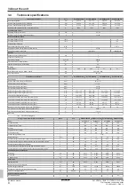
Model

Type

Domestic hot water

supply

Filling loop

D2TND012A4AB

D2TND012

Storage tank

External

D2TND018A4AB

D2TND018

Storage tank

External

D2TND024A4AB

D2TND024

Storage tank

External

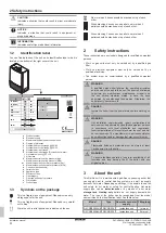
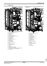
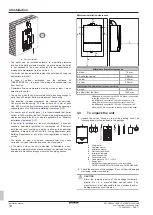
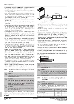
A control unit, which contains a user interface, controls the ignition,
safety systems, and other actuators. User interaction is provided via
that  user  interface,  which  is  composed  of  an  LCD  screen  and
buttons which is located on the front cover of the unit.

3.1

Safety systems

The unit is equipped with several safety systems, to protect it against
dangerous conditions:

Flue  safety  system

:  This  is  controlled  by  the  flue  gas  temperature

sensor  located  on  the  flue  outlet  part  of  the  boiler.  It  is  activated
when the flue gas temperature exceeds safety limits.

Overheating safety system

: This is controlled by the safety limiting

thermostat.  It  is  located  on  the  main  heat  exchanger  and  stops  the
unit  when  the  flow  temperature  reaches  100°C,  to  avoid  boiling  of
the water, which may damage the unit.

Pump  anti-blockage  system

:  The  pump  operates  for  30  seconds

every 24 hours during long periods of inactivity to ensure it does not
get stuck. To enable this function, the unit must be connected to the
power supply.

Three-way valve anti-blockage system

: In cases where the unit is

non-operational  for  prolonged  periods  of  time,  the  three-way  valve
switches its position every 24 hours to prevent it from getting stuck.
To  enable  this  function,  the  unit  must  be  connected  to  the  power
supply.

Safety  against  dry  operation

:  This  is  controlled  by  the  pressure

sensor.  It  turns  off  the  unit  and  ensures  system  safety  when  the
water pressure of the heating installation falls below 0.6 bar for any
reason.

Flame  ionisation  control

:  This  is  controlled  by  the  ionisation

electrode. It checks whether a flame forms on the burner surface or
not.  If  there  is  no  flame,  it  turns  the  unit  off  to  stop  gas  flow  and
warns the user.

High pressure protection

:

Pressure  sensor

:  When  heating  system  pressure  reaches

2.8  bar,  control  unit  stops  heating  operation  thus  preventing  the
pressure from rising.

Safety  valve

:  When  the  water  pressure  of  the  heating  circuit

exceeds  3  bar,  some  water  is  automatically  drained  from  the
safety valve to keep the pressure below 3 bar thus protecting the
boiler and heating installation.

Automatic  air  vents

:  There  are  two  air  vents;  one  on  the  pump,

other on the heat exchanger. They help discharging the air inside the
installation  and  heating  circuit  to  avoid  air  traps  and  consequent
operational problems.

Frost protection safety system

: This function protects the unit and

heating  installation  from  frost  damages.  It  is  controlled  by  the  flow
temperature  sensor,  which  is  located  at  the  outlet  of  the  main  heat
exchanger. This protection activates the boiler pump when the water
temperature drops below 13°C and it activates the burner when the
water temperature drops below 8°C. The unit keeps running until the
temperature reaches 20°C. To enable this function, the unit must be
connected to the power supply and its main gas valve must be open.
Any damage caused by frost is not covered by the warranty.

Low  voltage  safety  system

:  This  is  controlled  by  the  control  unit.

When the supply voltage drops below 170 V, the boiler goes to error
mode. It is a blocking error and the boiler will operate without reset

after  supply  voltage  is  above  180  V.  It  is  recommended  to  use  a
voltage regulator of suitable power and type in locations with voltage
fluctuations below this limit for faultless operation.

High  electric  supply  current  protection  system

:  A  fuse  on  the

control  unit  protects  equipment  and  wiring  against  the  damaging
effects  of  electrical  faults  which  is  caused  by  excess  currents,  and
disables  equipment  which  is  faulty.  The  fuse  "blows"  (opens)  when
the current carried exceeds the rated value for an excessive time.

Automatic  by-pass  system

:  This  ensures  that  the  flow  is  at  all

times  continued,  to  avoid  overheating  of  the  heat  exchanger.  This
system  is  also  supported  with  a  special  by-pass  function  in  the
control unit software.

Combustion control safety system

: Boiler control unit monitors the

flame  to  avoid  bad  combustion  and  risky  conditions.  It  also  makes
self-inspection against its own malfunctioning and to keep emissions
always at a low level.
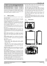
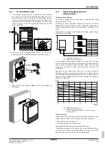
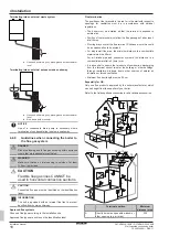
3.2

Dimensions

Top view

200

DN100

127

200

Front view and right side view

255.5

400

590

613.7

Bottom view of model D2CND024A1AB

53

65

61

22.4

161.7

105.8

101.4

71.9

65.1

Summary of Contents for D2CND024A4AB

Page 1: ...Installation manual Wall mounted condensing boiler English Installation manual Wall mounted condensing boiler D2CND024A1AB D2CND024A4AB D2TND012A4AB D2TND018A4AB D2TND024A4AB...

Page 2: ...tiivsete dokumentidega kui neid kasutatakse vastavalt meie juhenditele atitinka emiau nurodytus standartus ir arba kitus norminius dokumentus su s lyga kad yra naudojami pagal m s nurodymus tad ja lie...

Page 3: ...essure 29 Disposal Old units must be appropriately disposed of in accordance with local and national regulations The components are easy to separate and the plastics are marked This allows the various...

Page 4: ...2 Safety instructions These instructions are exclusively designed for qualified competent persons Work on gas units must only be carried out by a qualified gas fitter Work on electrical equipment must...

Page 5: ...rising Safety valve When the water pressure of the heating circuit exceeds 3 bar some water is automatically drained from the safety valve to keep the pressure below 3 bar thus protecting the boiler a...

Page 6: ...TND012 024A4AB Wall mounted condensing boiler 3P469346 3N 2019 11 Bottom view of model D2CND024A4AB 53 161 7 105 8 101 4 22 4 65 61 71 9 65 1 Bottom view of models D2TND012A4AB D2TND018A4AB and D2TND0...

Page 7: ...Return temperature sensor s Silencer t Automatic air vent pump u Water pressure sensor v By pass w Boiler pump x Domestic hot water flow sensor y Domestic hot water flow limiter z Internal filling val...

Page 8: ...x m h 0 12 0 46 0 12 0 69 0 12 0 96 0 12 0 96 Combustion products mass flow rate min max G20 g s 1 32 5 12 1 32 7 78 1 32 10 75 1 32 10 75 Combustion products mass flow rate min max G31 g s 1 23 4 77...

Page 9: ...aters 50 C return temperature at heater inlet 4 Installation 4 1 To open the unit WARNING Only qualified competent persons are allowed to open the unit Certain actions explained in this document such...

Page 10: ...current I E E Wiring Regulations local Building Regulations or any other local regulations currently in service The intake air must not include chemicals that may cause corrosion toxic gas formation a...

Page 11: ...height and related system charge pressure are given below h p 6 m 0 8 bar 7 m 0 9 bar 8 m 1 0 bar 9 m 1 1 bar 10 m 1 2 bar 11 m 1 3 bar 12 m 1 4 bar 13 m 1 5 bar h h System water height m p System cha...

Page 12: ...ted to 50 C and the pump operation temperature difference must be adjusted to 10 Kelvin in the service settings menu To change this setting refer to the servicing instructions WARNING Make sure parame...

Page 13: ...d Note Optional Daikin connection kit can be used and it is recommended to use it 4 8 2 Guidelines when connecting the gas piping This unit is designed to be operated with natural gas or LPG The prese...

Page 14: ...ar preheating of the domestic hot water from a solar tank install the thermostatic mixing valve at the domestic hot water outlet and inlet 4 8 4 Guidelines when connecting the electrical wiring DANGER...

Page 15: ...the options that are to be connected to the internal connectors must pop out from the inside of the unit via cable glands Cable glands that are sent with the unit must be assembled to the bottom shee...

Page 16: ...4AB Wall mounted condensing boiler 3P469346 3N 2019 11 4 8 6 Wiring diagram DANGER RISK OF ELECTROCUTION Disconnect the power supply for more than 10 minutes before servicing Models D2CND024A1AB and D...

Page 17: ...Ext3 X1M Daikin room thermostat Ext4 X2M External power output 230 V AC Ext5 X2M Reserved not in use X1M X4 X11 X12 Low voltage terminal strip X2M X1 X2 High voltage terminal strip 4 8 7 Guidelines wh...

Page 18: ...pes are written on the identification label Flue termination The positions of the terminals in the roof or in the wall with respect to openings for ventilation must be in accordance with national regu...

Page 19: ...ith a negative pressure area and therefore a plume management kit MUST be fitted 4 8 10 Applicable flue systems In this part information about different flue systems are given The mounting instruction...

Page 20: ...e Flat roof outlet kit f 90 elbow 60 100 g 45 elbow 60 100 h 30 elbow 60 100 i Extension 60 100 L 500 1000 mm Allowable flue length for C33x D2T H D2C Concentric 60 100 mm 12 5 m 7 6 m Concentric 80...

Page 21: ...ne the correct diameters and lengths of the flue system For D2T H Nominal combustion products temperature 77 C Combustion products mass flow rate 10 75 g s Overheat combustion products temperature 90...

Page 22: ...use flue outlet duct length must be shortened with the same length Type C83x twin pipes flue system The boiler draws combustion air from outside via a separate supply pipe routed through the external...

Page 23: ...69 2 DN 80 Flex square and rough 130 17 0 60 0 DN 80 Flex square and rough 120 12 2 43 0 DN 80 Star square and rough 140 47 5 167 8 DN 80 Star square and rough 120 33 3 117 9 Allowable flue length fo...

Page 24: ...EKFGP4801 1000 mm EKFGP4802 Flue part Order code Tile roof outlet kit 60 100 18 22 EKFGS0518 23 27 EKFGS0519 25 45 EKFGP7910 43 47 EKFGS0523 48 52 EKFGS0524 53 57 EKFGS0525 Tile roof outlet kit 80 12...

Page 25: ...ition 4 Connect the filling loop to the valve 7 and valve 8 5 Set valves 1 3 5 6 and 8 to open position 6 Slowly open the valve 7 until pressure reaches a value around 0 8 bar for system heights up to...

Page 26: ...3 Choose C parameters via left dial and press the Enter button 4 Choose CE and press the Enter button It will ask for password again Choose the password 115 and press the Enter button 5 Choose C0 and...

Page 27: ...The status indicator will glow constantly in blue if flame is established icon will blink when central heating is active INFORMATION After first power ON the boiler does not increase its capacity abov...

Page 28: ...5 Check that domestic hot water temperature rise is around 34 C 6 Hand over to the user After completing the installation and commissioning of the system the installer should hand over to the househo...

Page 29: ...rson who commissioned the boiler as a means of demonstrating compliance with the appropriate Building Regulations and then handed to the customer to keep for future reference GAS BOILER SYSTEM COMMISS...

Page 30: ...co uk It is recommended that your heating system is serviced regularly and that the appropriate Service Interval Record is completed Service Provider SERVICE RECORD SERVICE 01 AND Where Possible AND S...

Page 31: ......

Page 32: ...ANBUL T RK YE Tel 0216 453 27 00 Faks 0216 671 06 00 a r Merkezi 444 999 0 Web www daikin com tr G lsuyu Mahallesi Fevzi akmak Caddesi Bur ak Sokak No 20 34848 Maltepe 3P469346 3N 2019 11 Copyright 20...

Reviews: